JAJSN98E May   2020  – February 2024 UCC5350-Q1

PRODUCTION DATA  

  1.   1
  2. 特長
  3. アプリケーション
  4. 概要
  5. 概要 (続き)
  6. Pin Configuration and Function
  7. Specifications
    1. 6.1  Absolute Maximum Ratings
    2. 6.2  ESD Ratings
    3. 6.3  Recommended Operating Conditions
    4. 6.4  Thermal Information
    5. 6.5  Power Ratings
    6. 6.6  Insulation Specifications for D Package
    7. 6.7  Insulation Specifications for DWV Package
    8. 6.8  Safety-Related Certifications For D Package
    9. 6.9  Safety-Related Certifications For DWV Package
    10. 6.10 Safety Limiting Values
    11. 6.11 Electrical Characteristics
    12. 6.12 Switching Characteristics
    13. 6.13 Insulation Characteristics Curves
    14. 6.14 Typical Characteristics
  8. Parameter Measurement Information
    1. 7.1 Propagation Delay, Inverting, and Noninverting Configuration
      1. 7.1.1 CMTI Testing
  9. Detailed Description
    1. 8.1 Overview
    2. 8.2 Functional Block Diagram
    3. 8.3 Feature Description
      1. 8.3.1 Power Supply
      2. 8.3.2 Input Stage
      3. 8.3.3 Output Stage
      4. 8.3.4 Protection Features
        1. 8.3.4.1 Undervoltage Lockout (UVLO)
        2. 8.3.4.2 Active Pulldown
        3. 8.3.4.3 Short-Circuit Clamping
        4. 8.3.4.4 Active Miller Clamp
    4. 8.4 Device Functional Modes
      1. 8.4.1 ESD Structure
  10. Application and Implementation
    1. 9.1 Application Information
    2. 9.2 Typical Application
      1. 9.2.1 Design Requirements
      2. 9.2.2 Detailed Design Procedure
        1. 9.2.2.1 Designing IN+ and IN– Input Filter
        2. 9.2.2.2 Gate-Driver Output Resistor
        3. 9.2.2.3 Estimate Gate-Driver Power Loss
        4. 9.2.2.4 Estimating Junction Temperature
      3. 9.2.3 Selecting VCC1 and VCC2 Capacitors
        1. 9.2.3.1 Selecting a VCC1 Capacitor
        2. 9.2.3.2 Selecting a VCC2 Capacitor
        3. 9.2.3.3 Application Circuits with Output Stage Negative Bias
      4. 9.2.4 Application Curve
  11. 10Power Supply Recommendations
  12. 11Layout
    1. 11.1 Layout Guidelines
    2. 11.2 Layout Example
    3. 11.3 PCB Material
  13. 12Device and Documentation Support
    1. 12.1 Device Support
      1. 12.1.1 サード・パーティ製品に関する免責事項
    2. 12.2 Documentation Support
      1. 12.2.1 Related Documentation
    3. 12.3 Certifications
    4. 12.4 ドキュメントの更新通知を受け取る方法
    5. 12.5 サポート・リソース
    6. 12.6 Trademarks
    7. 12.7 静電気放電に関する注意事項
    8. 12.8 用語集
  14. 13Revision History
  15. 14Mechanical, Packaging, and Orderable Information

パッケージ・オプション

メカニカル・データ(パッケージ|ピン)
サーマルパッド・メカニカル・データ
発注情報

概要

UCC5350-Q1 はシングル チャネルの絶縁ゲート ドライバで、5A ソースおよび 5A シンクの最小ピーク電流を持ち、MOSFET、IGBT、SiC MOSFET を駆動するよう設計されています。UCC5350-Q1 には、ミラー クランプまたは分割出力のオプションがあります。CLAMP ピンを使ってトランジスタのゲートを内部 FET と出力に接続することで、ミラー電流による誤ターンオンを防止できます。分割出力付きの製品を使うと、ゲート電圧の立ち上がり / 立ち下がり時間を OUTH および OUTL ピンで個別に制御できます。

製品情報
部品のバージョン 特長 パッケージ(1) 本体サイズ (公称)
UCC5350MC-Q1 ミラー クランプ、12V UVLO DWV SOIC-8 7.5mm × 5.85mm
D SOIC-8 3.91mm x 4.9mm
UCC5350SB-Q1 分割出力、8V UVLO D SOIC-8 3.91mm x 4.9mm
供給されているすべてのパッケージについては、セクション 14 を参照してください。
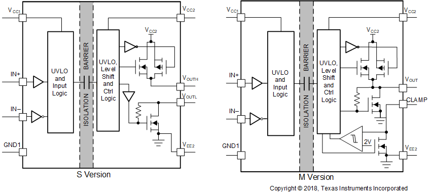
GUID-20210719-CA0I-BGTZ-CJSQ-9XXR2JVCJJTF-low.gif 機能ブロック図 (S、M バージョン)