JAJU446A December 2017 – January 2022
- 概要
- Resources
- 特長
- アプリケーション
- 5
- 1 System Description
- 2 System Overview
- 3 Circuit Design
- 4 Host Interface
- 5 Hardware Functional Block
- 6 Getting Started Application GUI
- 7 Testing and Results
- 8 Design Files
- 9 Software Files
- 10Related Documentation
- 11About the Authors
- 12Revision History
6 Getting Started Application GUI
The TIDA-01022 board requires three application software GUIs for validation: HSDC TID GUI, HSDC Pro GUI, and the LMK61xx Oscillator Programming Tool.
- Use the HSDC TID GUI to configure the data converter (ADC12DJ3200), clocking devices (LMK4828, LMX2594, and LMK61E2), and digital VGA (LMH6401). Use the low-level page to program the device with the respective configuration file. Download the latest HSDC TID GUI software at: http://www.ti.com/lit/zip/tidcdr5.
- Use the HSDC Pro GUI to capture the digitized data with the assistance of a TSW14J56 capture card and provide a spectrum and time domain plot. Download the latest HSDC Pro GUI software at: http://www.ti.com/tool/dataconverterpro-sw.
- Use the LMK61xx Oscillator Programming Tool to program the LMK61E2 device. Download the latest LMK61xx software at http://www.ti.com/lit/zip/snac074.
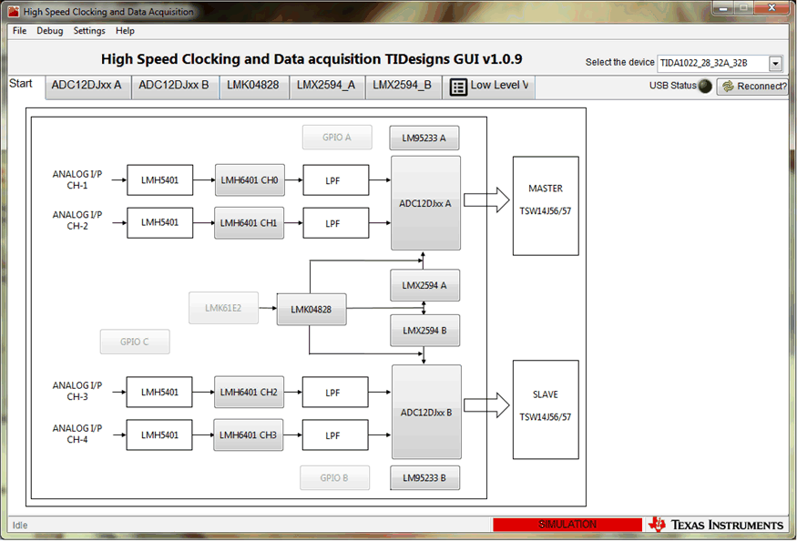
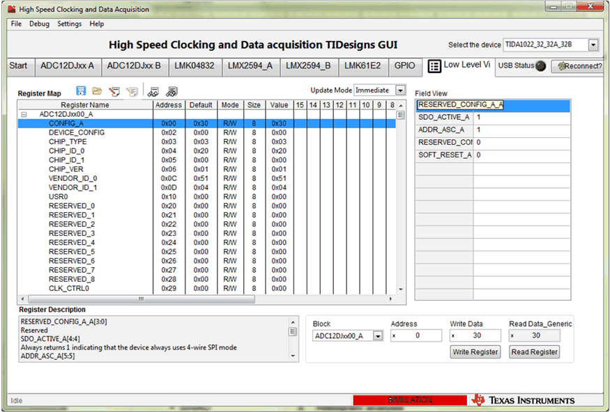
Figure 6-1 and Figure 6-2 show screenshots of starting the HSDC TID GUI configuration and the programming tab for the low-level view, respectively.
 Figure 6-1 HSDC TID GUI—Top Level Navigation View
 Figure 6-2 HSDC TID GUI—Low-Level Programming View
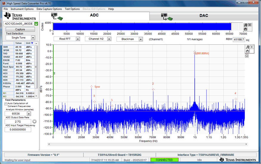
Figure 6-3 shows the ADC capture screen in the HSDC Pro GUI.
 Figure 6-3 HSDC Pro ADC Capture GUI (Spectrum, Time Domain)