SLOA289B May 2020 – September 2021 66AK2H06 , 66AK2H12 , 66AK2H14 , ADS8588H , AMC3301 , ISO224 , ISO7740 , ISO7741 , ISO7742 , LMZ30604 , SN65LVDS047 , SN65LVDS048A , UCC12040 , UCC12050
- Trademarks
- 1HVDC Power Transmission Overview and Architecture
- 2HVDC Transmission System (HVDC station)
- 3HVDC transmission station - Control and Protection (C and P)
- 4HVDC Transmission Control and Protection – System Level Block Diagram
- 5TI Solutions for HVDC Transmission Station Control and Protection
- 6Summary
- 7TI Reference Designs
- 8Additional References
- 9Revision History
4 HVDC Transmission Control and Protection – System Level Block Diagram
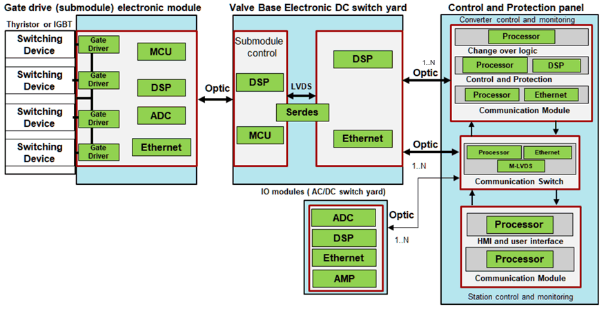
Figure 4-1 shows the control and protection block diagram for an HVDC station. Many of the equipment is placed within the control panel and some of the are placed close to the equipment being protected.
 Figure 4-1 HVDC Control and Protection System Block Diagram
Within the HVDC stations and the control panel, the following modules are interconnected to perform the required protection and control functions
Table 4-1 HVDC Station Modules Description
| Modules | Application | Location |
|---|---|---|
| Gate drive | Drives the Thyristor or IGBT module. Implements logic for gate drive, temperature and voltage measurement. Also called as submodules | Each IGBT or thyristor sub module has an associated gate drive unit. The number of gate drive boards depends on the converter voltage and power rating. |
| Valve control | A number of submodules are connected in series as a valve. Valve control electronics is used to provide command to the gate drive board control. | Each valve may contain one or more valve control electronics depending on the HVDC rating. |
| Converter and pole control | A converter bridge consists of 6 or more valves. The converter control computes the required electrical parameters and provides the required control command to the valve control. Pole control manages the grid AC voltage to maintain the configured DC output voltage. | The converter and pole control electronics is part of the control and protection panel. Multiple digital signal processing modules are integrated as converter and pole control module. Redundancy is provided to improve performance and enhance reliability. |
| Station level control and protection | Controls harmonics and reactive power by controlling the capacitor banks and filters. Protects the HVDC station during normal and abnormal operation | Part of the control and protection panel. Multiple digital signal processing modules are integrated as converter and pole control module. Redundancy is provided to improve performance and enhance reliability. |
| Communication switch | Connects different systems within the HVDC station using high speed fiber optic based Ethernet interface | Part of the control and protection panel. Multiple communication switches with redundancy are used. |
| Analog input/output (I/O) module | Use to measure the electrical parameters on the HVDC line, converter transformer, reactors, breakers, capacitor banks and filters for protection and monitoring | Connected along the HVDC station near to the equipment to be monitored and the numbers depends upon the power rating |