SLUP409B April 2022 – April 2024 TPS543320 , TPS543620 , TPS543820 , TPS62913 , TPS62916
- 1
- Abstract
- 1 Introduction
- 2 DC/DC Converters are Noisy
- 3 Power-Supply Output Voltage Ripple and Noise Degrade ADC Performance
- 4 Minimizing Low-Frequency Noise Requires Dedicated Low-Noise IC Technologies
- 5 Traditional Approaches to Reducing Ripple
- 6 Using Smaller Capacitors in Parallel
- 7 Larger Inductance
- 8 Adding a Feedthrough Capacitor
- 9 Adding a Ferrite Bead
- 10Layout Techniques
- 11Silicon Solutions
- 12Conclusions
6 Using Smaller Capacitors in Parallel
Instead of using a single larger ceramic capacitor, another method uses multiple ceramic capacitors in parallel that are physically smaller and have a lower capacitance on the output and lower parasitic inductance. This lower capacitance and parasitic inductance increase the self-resonant frequency of the capacitor. Above the self-resonant frequency, the capacitor’s parasitic inductance limits its impedance.
A lower parasitic inductance and a higher self-resonant frequency decrease the total impedance of the output capacitors.
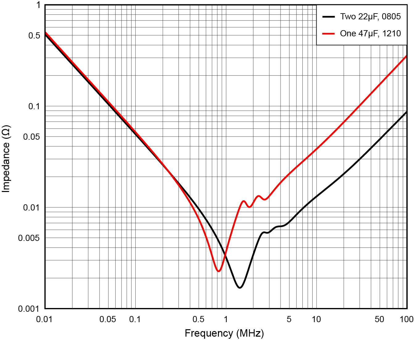
To illustrate this concept, Figure 9 shows the impedance of two 0805 22-µF capacitors in parallel vs. a single 1210 47-µF capacitor. Below 100kHz, the capacitance sets the impedance, so there is no significant difference between the two impedances. The single 47-µF capacitor has a lower self-resonant frequency of approximately 800kHz, while the 22-µF capacitors have a self-resonant frequency greater than 1 MHz. As a result, the 22-µF capacitors have a minimum impedance of less than 2mΩ, while the 47-µF capacitor has a minimum impedance greater than 2mΩ. The minimum impedance occurs at the self-resonant frequency, so selecting a capacitor with a self-resonant frequency near the switching frequency will provide the most filtering at the switching frequency. Above the self-resonant frequencies, the impedance of the 22-µF capacitors is approximately one-third the impedance of the 47-µF capacitor.
 Figure 9 Impedance of two 0805 22-µF
ceramic capacitors vs. one 1210 47-µF ceramic capacitor.
Figure 9 Impedance of two 0805 22-µF
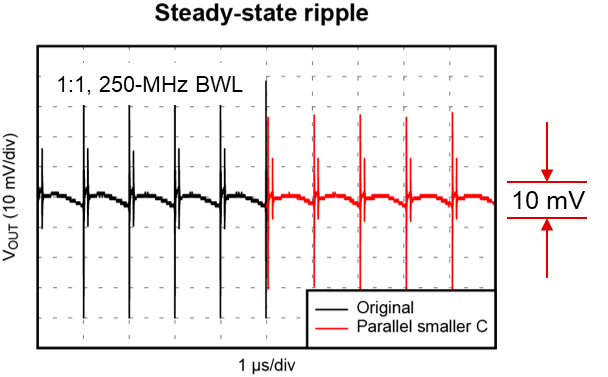
ceramic capacitors vs. one 1210 47-µF ceramic capacitor.Figure 10 shows what happens when you replace the one 47-µF capacitor in the schematic shown in Figure 5 with two 22-µF capacitors. In the output ripple graph shown in Figure 10, the black curve on the left is the original output ripple and the red curve on the right is ripple with the modified output capacitors. This waveform shows reduced high-frequency content in the output ripple.
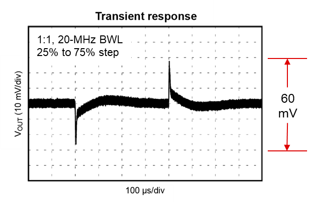
In the transient response graph shown in Figure 11, the performance is about the same, but lower high-frequency ripple is visible. And in Figure 12, the effect of the reduced impedance across the entire frequency range is more clear. The red curve in Figure 12 shows a reduction of the fundamental peak at the 1-MHz fSW and its harmonics to about two-thirds their original values.
Figure 9 shows that the impedance of a single 47-µF capacitor is the same as two 22-µF capacitors at the 1-MHz switching frequency. This apparent conflict likely occurs because the impedance curves in Figure 9 do not include the effects of PCB parasitics on the filter’s impedance.
 Figure 10 Smaller capacitor output
ripple.
 Figure 11 Smaller capacitor transient
response.
 Figure 12 Smaller capacitor output
FFT.
Figure 12 Smaller capacitor output
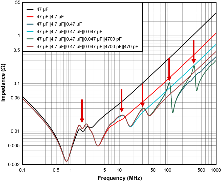
FFT.Although paralleling smaller capacitors can provide higher-frequency broadband filtering, consider the effect of increased impedance caused by inter-capacitance resonance peaks when adding a new capacitor size and value to the output capacitor network. Spacing capacitors in a 10-to-1 ratio can increase the likelihood of this effect.
Figure 13 compares the impedance of capacitor networks with different parallel combinations of 47-µF, 4.7-µF, 0.47-µF, 0.047-µF, 4,700-pF and 470-pF capacitors. The red arrows in the figure point to the increased impedance at the intercapacitance resonant peaks. The effect is more pronounced as the self-resonant frequency of the capacitor increases, such as with the 4,700-pF and 470-pF capacitors. If the output contains ripple or noise at the frequency of the peaks, that ripple or noise would increase as a result of adding the capacitor.
Spacing capacitor values in a 2-to-1 to 3-to-1 ratio can help reduce the peaks caused by intercapacitance resonance. Additionally, when paralleling multiple capacitors, it is important to be aware of the frequency of the noise that needs filtering. We recommend adding a capacitor with a self-resonant frequency as close as possible to the frequency of the noise, and testing multiple adjacent values to find the best value. Measuring an FFT of the output ripple can be useful when selecting the most effective capacitor.
 Figure 13 Intercapacitance resonance
peaks when paralleling capacitors in 10-to-1 ratio.
Figure 13 Intercapacitance resonance
peaks when paralleling capacitors in 10-to-1 ratio.Paralleling smaller capacitors offers a relatively small reduction in output ripple, and this approach alone is likely not sufficient to meet ripple requirements of 1mV or lower. It is a simple schematic change, however, and uses standard ceramic capacitors. Additionally, given the higher fSW trend, it’s a good idea to consider smaller capacitors with a higher self-resonant frequency for all designs. A trade-off when adding smaller capacitors to a design is that it can result in increased costs, because of the increased number of new components in the bill of materials.