SLVAE59A February 2019 – April 2022 DRV8242-Q1 , DRV8243-Q1 , DRV8244-Q1 , DRV8245-Q1 , DRV8343-Q1 , DRV8702-Q1 , DRV8702D-Q1 , DRV8703-Q1 , DRV8703D-Q1 , DRV8803 , DRV8804 , DRV8805 , DRV8806 , DRV8860 , DRV8873 , DRV8873-Q1 , DRV8874 , DRV8874-Q1 , DRV8876 , DRV8876-Q1 , DRV8935 , DRV8955
4.3 Half-Bridge Driving
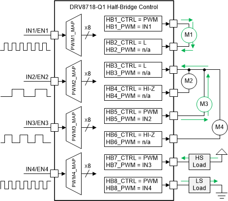
Half-bridge driving can be very useful as it provides flexibility in load configuration, and H-bridge solutions can be configured as multiple half-bridges to drive multiple solenoids. As mentioned before, the DRV8714-Q1 and DRV8718-Q1 gate drivers support this configuration, along with PWM mapping feature, as shown in Figure 4-5
 Figure 4-5 Half-Bridge Control
The DRV8343-Q1 can control up to three different solenoids in a high-side PWM and low-side cutoff configuration. In this mode the DRV8343-Q1 will automatically insert dead time when switching and handle the protections for over current protection (OCP), short to battery, and short to GND faults. In Independent Half-Bridge PWM mode, the INHx pin controls each half-bridge independently and supports two output states: low or high. The corresponding INHx and INLx signals control the output state as listed in . The INLx pin is used to change the half-bridge to high impedance. If the high-impedance (Hi-Z) state is not required, tie all INLx pins logic high.
| INLx | INHx | GLx | GHx |
|---|---|---|---|
| 0 | x | L | L |
| 1 | 0 | H | L |
| 1 | 1 | L | H |
Combinations of Half-Bridge and Independent MOSFET drive modes are available where two of the phases will be in Independent Half-Bridge mode and the last phase in Independent MOSFET mode. This allows a total of four solenoids to be driven at the same time individually, two in push-pull configuration, one in high-side configuration, and one in low-side configuration. In these modes, the two phases in independent Half-Bridge mode control the independent fault handling and dead time enforcement is done by the device. The dead time insertion by the device is bypassed for the phase in Independent MOSFET mode.
For lower current applications, the DRV824x-Q1 and DRV887x-Q1 are device families of integrated H-Bridge drivers which scale by RDSON. These drivers can also be configured to drive two solenoids in Independent Half Bridge mode. The MOSFETs are built into the devices to simplify the design and decrease board space.
The DRV824x-Q1 family can support independent half-bridge mode to drive several load configurations. A low-side configuration example is shown in Figure 4-6.
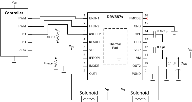
Figure 4-7 shows the application schematic configured to drive two solenoids in Independent Half-Bridge mode.
 Figure 4-7 Application Schematic for
DRV887x to Drive Two Solenoids
Figure 4-7 Application Schematic for
DRV887x to Drive Two SolenoidsTable 4-3 shows the truth table for Independent Half-Bridge mode.
| nSleep | INx | OUTx | Description |
|---|---|---|---|
| 0 | X | Hi-Z | Sleep, (H-Bridge, Hi-Z) |
| 1 | 0 | L | OUTx Low-side On |
| 1 | 1 | H | OUTx High-side On |
The DRV8706-Q1 is a small single H-Bridge gate driver that uses four external N-channel MOSFETs that can control up to two solenoids or relays independently. Figure 4-8 shows control of Independent Half Bridge mode. Table 4-4 shows the control table for DRV8706-Q1 in Independent Half Bridge mode. In this mode, the device does not perform PWM current regulation or current chopping.
| nHIZx | IN1x | GHx | GLx | SHx |
|---|---|---|---|---|
| 0 | x | L | L | Z |
| 1 | 0 | L | H | L |
| 1 | 1 | H | L | H |
 Figure 4-8 Half-Bridge Control