SLVAF10 March 2021 TPS1H000-Q1 , TPS1H100-Q1 , TPS1H200A-Q1 , TPS1HA08-Q1 , TPS1HB08-Q1 , TPS1HB16-Q1 , TPS1HB35-Q1 , TPS1HB50-Q1 , TPS2H000-Q1 , TPS2H160-Q1 , TPS2HB16-Q1 , TPS2HB35-Q1 , TPS2HB50-Q1 , TPS4H000-Q1 , TPS4H160-Q1
1 Introduction
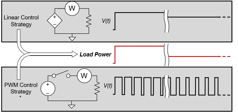
Pulse-width modulation (PWM) is an indispensable technique for controlling load power when driving off-board loads with high-side switches (HSS). By adjusting PWM duty cycle, average load power can be controlled with accuracy and much more efficiently than designs which rely on linear regulation of voltage or current to the load. PWM control can be used to increase product functionality — for example, to enable a vehicle owner to choose the heat level in a heated seat or adjust the brightness of footwell lighting. Figure 1-1 compares PWM and linear control schemes which result in the same load power.
PWM duty cycle may be software or hardware defined and can be varied in real-time. Apart from the limitations of the high-side switch or nuances of the load, the average power delivered to the load is virtually independent of PWM frequency. This allows for flexibility in the system design.
 Figure 1-1 PWM and Linear Control of Load Power