SLVUBT8B November 2020 – June 2022 LP8764-Q1 , TPS6594-Q1
- Scalable PMIC's GUI User’s Guide
- Trademarks
- 1 Introduction
- 2 Supported Features
- 3 Revisions
- 4 Overview
- 5 Getting Started
- 6 Quick-start Page
- 7 Register Map Page
- 8 NVM Configuration Page
- 9 NVM Validation Page
- 10Watchdog Page
- 11Additional Resources
- 12Appendix A: Troubleshooting
- 13Appendix B: Advanced Topics
- 14Appendix C: Known Limitations
- 15Appendix D: Migration Topics
- 16Revision History
6.2.4 GPIO
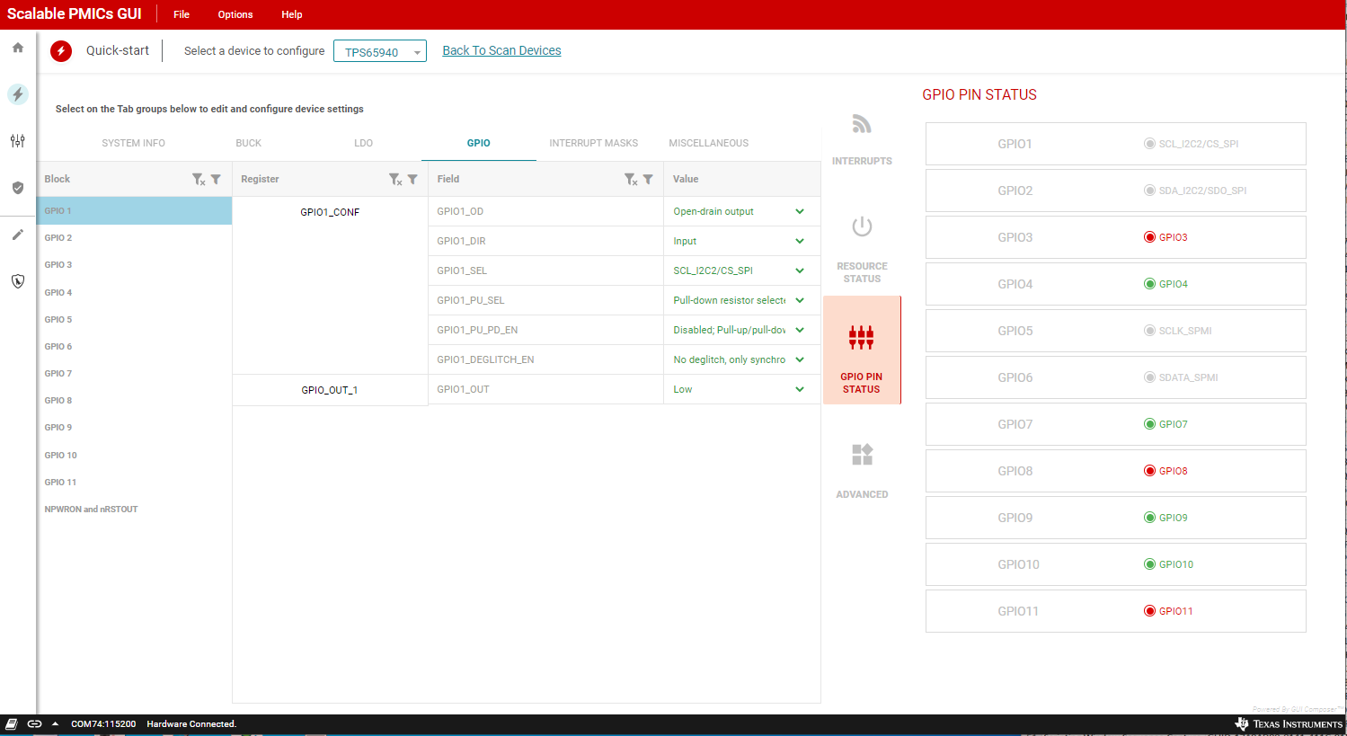
The GUI provides the interface to configure the PMIC GPIOs. When the GPIO is configured as an input, the GUI provides an additional mechanism to drive the GPIO from an associated AEVM pin and view the state change through the GPIO Status vertical tab on the right side of the page.
The PMIC GPIO can be configured as input or output or be mapped to internal functions within the PMIC. For this example, the PMIC is using GPIO1 and GPIO2 for the second I2C instance. The GPIO PIN STATUS window pane can be used to confirm the function and the level of each pin when configured as GPIO. The CONFIGURE GPIO LEVEL box appears, see Figure 6-7, when the GPIO direction is set to input to initially set the AEVM output level. Please ensure that the hardware platform is configured to support the intended GPIO operation.
When evaluating a multi-PMIC solution, the control of the AEVM outputs are only for the AEVM which is connected to the GUI (connected to the PC through the USB port).
The GPIO pin status, see Figure 6-7, indicates the function of the GPIO as well as the current state (high or low) of GPIO that are not configured for special functionality. The colors are gray, red, and green. In addition to the color, a text description to the right of each indicator is also provided.
 Figure 6-7 GPIO Configuration