SPRACU9 October 2021 F29H850TU , F29H859TU-Q1 , TMS320F2800152-Q1 , TMS320F2800153-Q1 , TMS320F2800154-Q1 , TMS320F2800155 , TMS320F2800155-Q1 , TMS320F2800156-Q1 , TMS320F2800157 , TMS320F2800157-Q1 , TMS320F280033 , TMS320F280034 , TMS320F280034-Q1 , TMS320F280036-Q1 , TMS320F280036C-Q1 , TMS320F280037 , TMS320F280037-Q1 , TMS320F280037C , TMS320F280037C-Q1 , TMS320F280038-Q1 , TMS320F280038C-Q1 , TMS320F280039 , TMS320F280039-Q1 , TMS320F280039C , TMS320F280039C-Q1 , TMS320F28384D , TMS320F28384D-Q1 , TMS320F28384S , TMS320F28384S-Q1 , TMS320F28386D , TMS320F28386D-Q1 , TMS320F28386S , TMS320F28386S-Q1 , TMS320F28388D , TMS320F28388S , TMS320F28P550SG , TMS320F28P550SJ , TMS320F28P559SG-Q1 , TMS320F28P559SJ-Q1 , TMS320F28P650DH , TMS320F28P650DK , TMS320F28P650SH , TMS320F28P650SK , TMS320F28P659DH-Q1 , TMS320F28P659DK-Q1 , TMS320F28P659SH-Q1
3 Program Descriptions
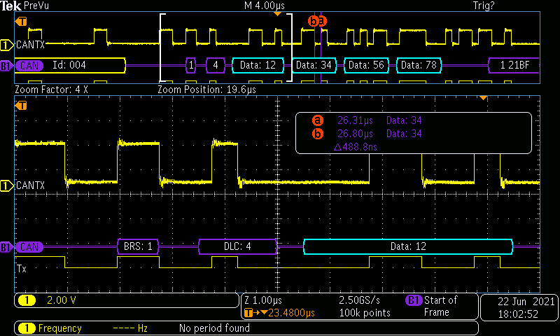
mcan_ex1_loopback.c – This example illustrates the loopback functionality of the MCAN module. The loopback operation is completely internal to the module. However, the transmitted data is visible in the MCANTX pin. An advantage of this testcase is that it does not need the transceiver, so it can run on boards like the controlCARD. To facilitate easy capturing of data on an oscilloscope, only four bytes of data are transmitted. However, it is transmitted as a CAN FD frame with Bit-rate switching. For more information, see Figure 3-1.
 Figure 3-1 Output From MCANTX Pin for
mcan_ex1_loopback.c
Figure 3-1 Output From MCANTX Pin for
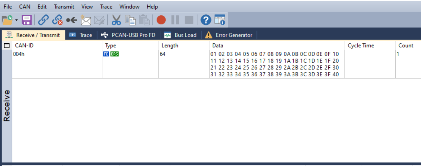
mcan_ex1_loopback.cFigure 3-2 shows the output of the CAN bus monitoring tool. Note that both FDF and BRS bits are flagged in the output. The program terminates after transmitting four bytes.
 Figure 3-2 Output of Bus-Monitoring Tool
for mcan_ex1_loopback.c
Figure 3-2 Output of Bus-Monitoring Tool
for mcan_ex1_loopback.cmcan_ex3_transmit.c - This example demonstrates the MCAN External Transmit function. External communication is done between two CAN nodes. The receiving node could be another MCU or a CAN bus analysis tool capable of Receiving/ACKnowledging the transmitted frames. Both CAN nodes should connected through a CAN Transceiver. Nominal Bit Rate of 500 kbps and Data bit rate of 1 Mbps is used.
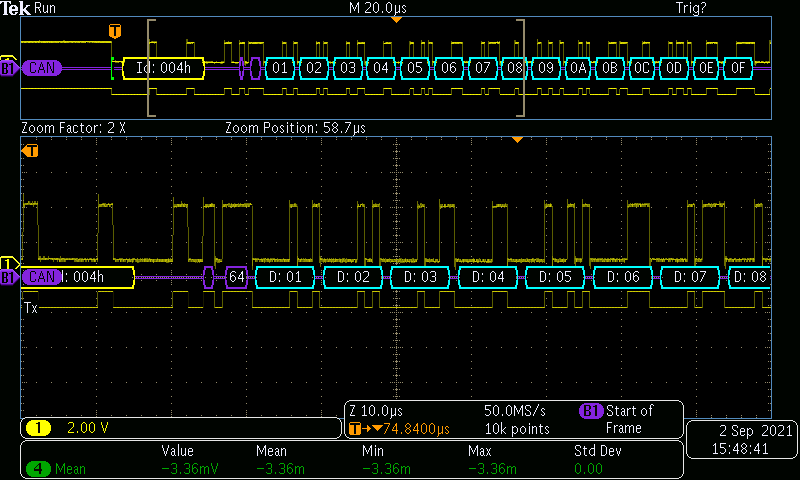
Standard Identifier (STD ID) 0x4 is transmitted with 64 data bytes one time. #defines that are not required for this test case have been commented out. However, they have been left in the code should the scope of this code be expanded to include Receive and FIFO functions.
 Figure 3-3 Output of Bus-Monitoring Tool
for mcan_ex3_transmit.c
 Figure 3-4 Output From MCANTX Pin for
mcan_ex3_transmit.c
Figure 3-4 Output From MCANTX Pin for
mcan_ex3_transmit.cmcan_ex4_receive.c - This example demonstrates the MCAN receive function. The transmitting node could be another MCU or a CAN bus analysis tool capable of transmitting CAN FD frames. Nominal Bit Rate of 500 kbps & Data bit rate of 1 Mbps is used. Only frames with a standard message ID of 0x4 is received. If another C2000 MCU with MCAN module is used as the transmitter, mcan_ex3_transmit.c can be run on it for the transmit function.
mcan_ex5_mask_filter_receive.c - This example demonstrates Reception (with mask filter) into RX-FIFO1. The transmitting node could be a CAN FD capable controller or a CAN bus analysis tool capable of transmitting CAN FD frames. Bits 0, 1 & 3 of the identifier are masked. So, these bits can have any value. This is achieved by using stdFiltelem.sfid1 = 00000001111b and stdFiltelem.sfid2 = 11111110100b (0 for “don’t care” ), which means any frame with an ID of 0000000x1xxb are received and stored into the FIFO. That is, frames with the following standard IDs are received: 0x004, 0x005, 0x006, 0x007, 0x00C, 0x00D, 0x00E, 0x00F. All other IDs are not received. Classic bit-mask filter is employed. This example may be used in conjunction with mcan_ex3_transmit. Nominal Bit Rate of 500 kbps and Data bit rate of 1 Mbps is used.
mcan_ex7_classic_transmit.c - This simple example demonstrates how to transmit classic CAN frames from the MCAN module. This example is very useful when the other node is only capable of processing classic CAN frames. This example is useful to ascertain the external communication capability of the MCAN node. Bit Rate configured is 500 kbps. A frame with an extended identifier of 0x15A5A5A5 is transmitted with 8 data bytes.
mcan_ex8_range_filter.c - This example demonstrates Reception (with range filter) into RX-FIFO1. The transmitting node could be a CAN FD capable controller or a CAN bus analysis tool capable of transmitting CAN FD frames. Only frames with extended IDs from 0x1FFFFF23 to 0x1FFFFF46 are received. Other IDs are not received. RXFIFO1 starts at an offset of 748 (2EC). MCAN Message RAM starts at 0x58000, so received messages will be copied starting at address 0x582EC. Note that as long as the respective ID bits match, "classic" CAN frames will also be received. Nominal Bit Rate of 500 kbps and Data bit rate of 1 Mbps is used.