SWRU546E October 2018 – May 2022 AWR6843 , AWR6843AOP , IWR6443 , IWR6843 , IWR6843AOP
- Trademarks
- 1Getting Started
-
2MMWAVEICBOOST
- 2.1 Hardware
- 2.2 Block Diagram and Features
- 2.3 Muxing Scheme for Multiple Sources
- 2.4 Using the MMWAVEICBOOST With the Starter Kit
- 2.5 Interfacing with the DCA1000EVM
- 2.6 Power Connections
- 2.7
Connectors
- 2.7.1 20-Pin LaunchPad and Booster Pack Connectors (J5, J6)
- 2.7.2 60-Pin High Density (HD) Connector (J4 and J17)
- 2.7.3 60-Pin High Density (HD) Connector (J10)
- 2.7.4 MIPI 60-Pin Connector (J9)
- 2.7.5 TI 14-Pin JTAG Connector (J19)
- 2.7.6 CAN Connector (J1 and J2)
- 2.7.7 Ultra-Miniature Coaxial Connector (J3)
- 2.8 Jumpers, Switches and LEDs
- 3xWR6843ISK / IWR6843ISK-ODS REV C
-
4xWR6843AOPEVM Rev G
- 4.1 Hardware
- 4.2 Block Diagram
- 4.3 PCB Storage and Handling Recommendations
- 4.4 Heat Sink and Temperature
- 4.5 xWR6843AOPEVM Antenna
- 4.6 Switch Settings
- 4.7 xWR6843AOPEVM Muxing Scheme
- 4.8 Modular, DCA1000EVM and MMWAVEICBOOST Mode
- 4.9 Known Issues: Spurious Performance
- 4.10 PC Connection
- 4.11 REACH Compliance
- 4.12 Regulatory Statements with Respect to the xWR6843AOPEVM Rev G
- 5xWR6843AOPEVM Rev F
- 6IWR6843ISK / IWR6843ISK-ODS (deprecated)
- 7IWR6843AOPEVM (Deprecated)
- 8TI E2E Community
- 9Certification Related Information
- Revision History
2.3 Muxing Scheme for Multiple Sources
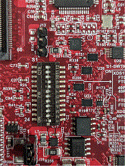
There are multiple sources as shown in Figure 2-4 such as 40 pin LP/BP, DCA1000 EVM, onboard FTDI and XDS110 that can control the Radar front-end chip in the starter kit. This is done with the help of mux scheme implemented on the MMWAVEICBOOST. Follow the switch settings as shown in Table 2-1 to avoid the conflicts. The most used configuration is the default position.
 Figure 2-4 Muxing Scheme
Table 2-1 shows the dip switch settings for multiple sources connecting to mmWave sensing device.
Table 2-1 Switch Settings
| Reference Designator | (Default Position) Position for STAND ALONE Mode (1) | Position for DCA1000 Mode | Position for 40-Pin LP/BP |
|---|---|---|---|
 |  |  | |
| S1.12 | ON | ON | ON |
| S1.11 | ON | ON | OFF |
| S1.10 | ON | ON | OFF |
| S1.9 | OFF | OFF | ON |
| S1.8 | OFF | OFF | ON |
| S1.7 | ON | OFF | OFF |
| S1.6 | ON | OFF | OFF |
| S1.5(2) | ON | ON | OFF |
| S1.4 | ON | OFF | ON |
| S1.3 | ON | ON | OFF |
| S1.2 | ON | ON | ON |
| S1.1 | OFF | OFF | OFF |
(1) Standalone mode means starter kit and MMWAVEICBOOST connected together.
(2) S1.5 has RS232 connections from 40 pin/FTDI/60 pin/XDS110, ON postion routes UART to XDS110 (Application/user UART COM port).
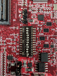
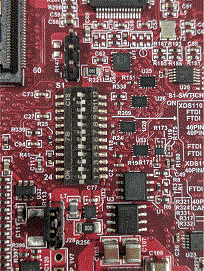
Table 2-2 shows the images of NRST, DIP switch settings, SOP lines, and power input locations on the physical board.
Table 2-2 Mux Selection Images
| Front | Rear | |
|---|---|---|
| Whole Board |  Figure 2-5 Front
 |  Figure 2-6 Rear Figure 2-6 Rear |
| Zoomed IN |  Figure 2-7 Front Figure 2-7 Front |