SWRU613 july 2023 AWRL1432
- 1
- Description
- Get Started
- Features
- 5
- 1Evaluation Module Overview
-
2Hardware
- 2.1 XWRL1432BOOST Antenna
- 2.2 EVM Mux Block Diagram
- 2.3 Switch Settings
- 2.4 LEDs
- 2.5 Connectors
- 2.6 USB Connector
- 2.7 DCA1000 HD Connector
- 2.8 Booster Pack Connector for the LaunchPad Connectivity
- 2.9 CANFD Connector
- 2.10 LIN PHY Connection
- 2.11 I2C Connections
- 2.12 XDS110 Interface
- 2.13 Flashing the Board
- 2.14 DCA1000EVM Mode
- 2.15 PCB Storage and Handling Recommendations:
- 3Software
- 4Hardware Design Files
- 5Additional Information
- 6References
3.1.1 XWRL1432 Demo Visualization Getting Started
Figure 3-1 Demo Visualization Getting
Started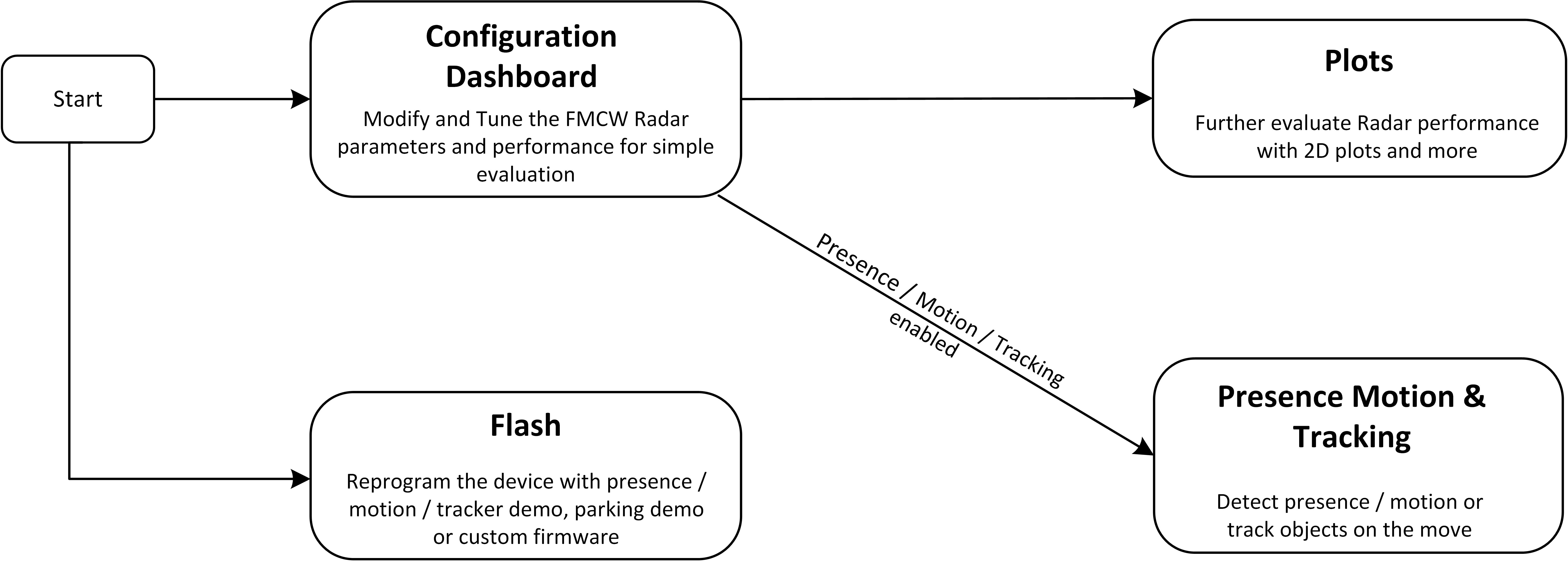
- Step1 : Connect the EVM to the PC via USB.
- Step 2 (Optional): Program a non-default
firmware / app-image.
- Navigate to the Flash tab.
- AUTO detect COM ports (press refresh icon) and select device COM port (if not already selected).
- Follow the subsequent steps shown in the Visualizer.
- Step 3: Configure Device.
- Navigate to the Configuration Dashboard tab.
- AUTO detect COM ports (press refresh icon) and select device COM port (if not already selected).
- Select preset configuration under Configuration Selection.
- Click on Send Selected Config.
- Step 4: Plots tab displays point cloud information.