TIDU312A May 2014 – November 2020
- Trademarks
- 1Introduction
- 2Software Overview
- 3Procedure for Running the Incremental Builds
- 4Test Results
- 5References
- 6Revision History
2.1 Software Control Flow
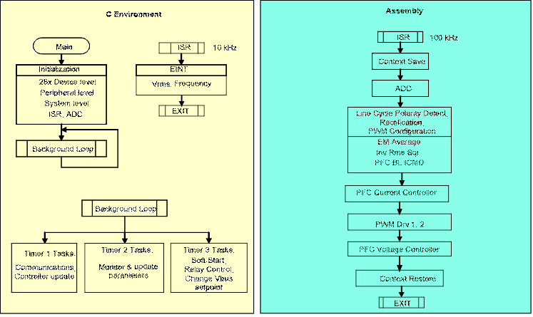
The C2000 BLPFC project mostly makes use of the “C-background/ASM-ISR” framework. The main fast ISR (100 kHz) runs in assembly environment. However, a slower ISR (10 kHz) is also run from C environment. This slow ISR is made interruptible by the fast ISR.
 Figure 2-1 BL PFC
Software Flow Diagram
Figure 2-1 BL PFC
Software Flow DiagramThe project uses C-code as the main supporting program for the application, and is responsible for all system management tasks, decision making, intelligence, and host interaction. The assembly code is strictly limited to the fast Interrupt Service Routine (ISR), which runs all the critical control code. Typically, this includes reading ADC values, input line cycle polarity detect, sensed line volt rectification, control calculations, and PWM updates. The slower ISR in the C environment calculates the RMS voltage and frequency of the input line voltage. Figure 2-1 depicts the general software flow for this project.
The key framework C files used in this project are:
-
BridgelessPFC-Main.c
This file is used to initialize, run, and manage the application.
-
BridgelessPFC-DevInit_F2802x.c or BridgelessPFC-DevInit_F2803x.c
Depending on the control card (F2802x or F2803x respectively) used in the BL PFC EVM one of these files will be in the Code Composer Studio™ project. This file is responsible for a one time initialization and configuration of the F280xx device, and includes functions such as setting up the clocks, PLL, GPIO, etc.
The fast ISR consists of a single file:
-
BridgelessPFC-DPL-ISR.asm
This file contains all time critical “control type” code. This file has an
initialization section (one time execute) and a run-time section that
executes at half the rate (100 kHz) as the PWM time-base (200 kHz) used to
trigger it.
The slow ISR consists of a single file:
-
SineAnalyzer.h
This file contains code for calculating the RMS voltage and frequency of the
input line voltage. This file has an initialization section (one time
execute) and a runtime section that executes at 10 kHz rate.
The Power Library functions (modules) are “called” from the fast ISR framework.
Library modules may have both a C and an assembly component. In this project, seven library modules are used. The C and corresponding assembly module names can be found in Table 2-1.
| C Configure Function | ASM Initialization Macro | ASM Run-Time Macro |
|---|---|---|
| PWM_1ch_UpDwnCnt_Cnf.c | PWMDRV_1ch_UpDwnCnt_INIT n | PWMDRV_1ch_UpDwnCnt n |
| ADC_SOC_Cnf.c | ADCDRV_1ch_INIT m,n,p,q | ADCDRV_1ch m,n,p,q |
| PFC_InvRmsSqr_INIT n | PFC_ InvRmsSqr n | |
| MATH_EMAVG_INIT n | MATH_EMAVG n | |
| PFC_BL_ICMD_INIT n | PFC_BL_ICMD n | |
| CNTL_2P2Z_INIT n | CNTL_2P2Z n |
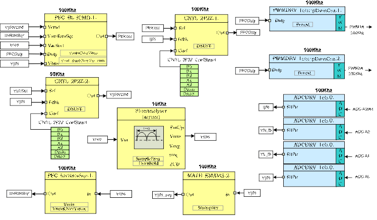
The assembly modules can also be represented graphically as seen in Figure 2-2.
 Figure 2-2 Software
Blocks
Figure 2-2 Software
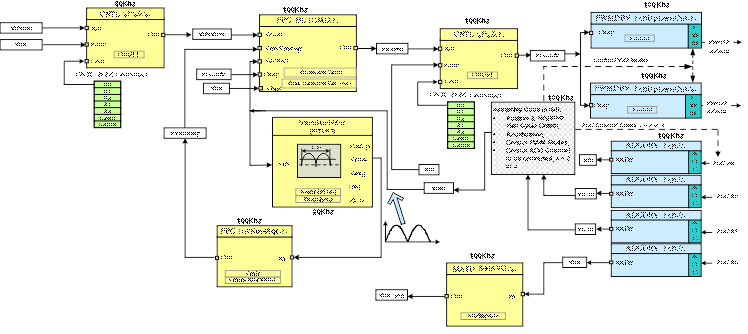
BlocksNote the color coding used for the modules in Figure 2-2. The blocks in ‘dark blue’ represent the on-chip hardware modules in C2000 controller. The blocks in ‘blue’ are the software drivers associated with these modules. The blocks in ‘yellow’ are part of the computation carried out on various signals. The controllers used for voltage and current loops have the form of a 2-pole 2-zero compensator. However these can be of other forms such as, PI, PID, 3-pole 3-zero or any other controller suitable for the application. The modular library structure makes it convenient to visualize and understand the complete system software flow as shown in Figure 2-3. It also allows for easy use and additions/deletions of various functions. This fact is amply demonstrated in this project by implementing an incremental build approach. This is discussed in more detail in Section 2.2.
 Figure 2-3 Software
Control Flow
Figure 2-3 Software
Control FlowAs mentioned inSection 1.1 the BL PFC system is controlled by two feedback loops. The outer voltage loop regulates the DC bus voltage, while a faster inner current loop wave shapes the input current in order to maintain a high input power factor. Figure 2-3 also gives the rate at which the software modules are executed. For example, the current controller is executed at a rate of 100 kHz (half of the PWM switching frequency) while the voltage controller is executed at 50kHz rate.