SBAA463A january 2021 – april 2023 TMAG5170 , TMAG5170-Q1 , TMAG5170D-Q1 , TMAG5173-Q1 , TMAG5273
4.1.3 Prototyping and Verification
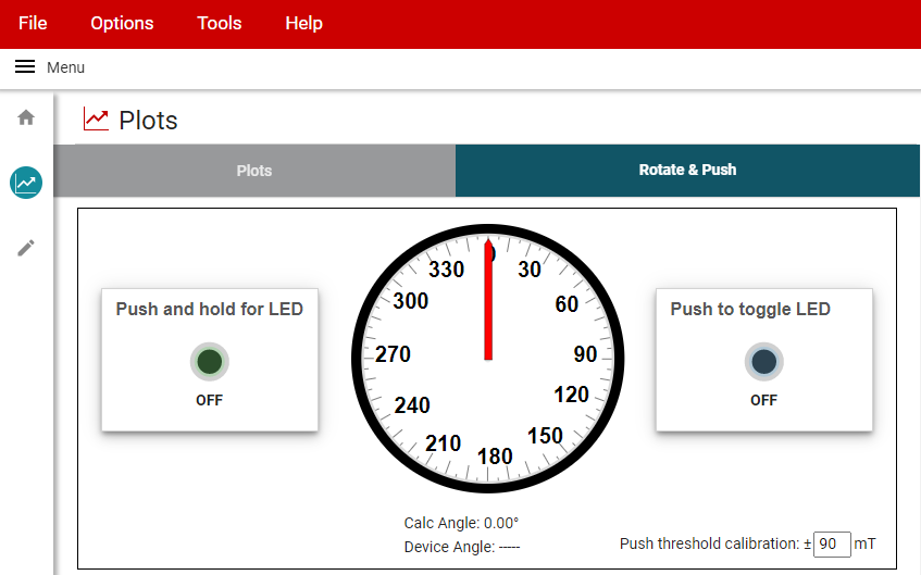
With the knob attachment mounted to the EVM, the GUI offers the option to capture and plot the outputs of each channel, or as an alternative, there is a visual interface which displays real time updates to the magnet angle.
 Figure 4-3 TMAG5170 Rotate &
Push GUI
Figure 4-3 TMAG5170 Rotate &
Push GUIThis output format helps to emulate the end application feel, but cannot tell us exact measurement errors.
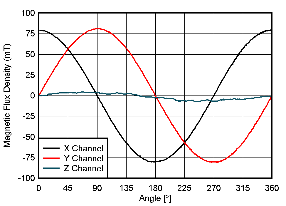
Conversely, we can capture the data from a large number of data samples and then use this to plot of X and Y input data against the output angle. With this approach, we can look for anomalous behavior that would be indicative of any non-linearity in the angular response of the device.
 Figure 4-4 TMAG5170 Knob
Attachment Measured Data
Figure 4-4 TMAG5170 Knob
Attachment Measured DataNotice here there are a few small irregularities, but over the course of a full rotation we see fairly smooth results that are very near to the pattern of the ideal input. This is primarily due to the handling of the knob impacting the sensor proximity and magnet tilt. There is also some offset which results with a detectable portion of the magnetic field in the Z-direction.
Also notice that the peak magnitude does not match the simulated value here. During the prototype build it was discovered that the spring used in the original knob design needed to be replaced, and that the replacement spring was somewhat ferromagnetic. Despite this interference, the end result is still capable of detecting a reasonably accurate angle for this use case. When designing any application, it is always recommended to consider the impact of external materials on the observed magnetic field.