SBAA463A january 2021 – april 2023 TMAG5170 , TMAG5170-Q1 , TMAG5170D-Q1 , TMAG5173-Q1 , TMAG5273
4.2.2 Accuracy Verification
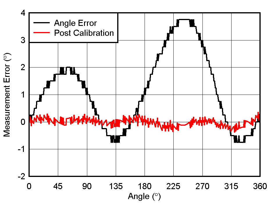
When performing angle calculations using the simulated data, the angle error is near zero for this approximate location and is negligible in comparison the 0.25 degree resolution of TMAG5170. While the initial measurement data shows outputs that appear to meet expectations and are sinusoidal in nature, we also find that when the angular position is calculated and plotted against the precise angular position that we see some unexpected angle error. This is represented as Angle Error in Figure 4-7.
 Figure 4-7 Measured Off-Axis Angle
Error
Figure 4-7 Measured Off-Axis Angle
ErrorThe angle error observed in the physical setup, even after adjusting inputs for ideal matching, is related to mechanical errors in the setup. Minor amounts of magnet tilt and wobble have produced the cyclically repeating error.
There are a variety of approaches which might be used to further calibrate out this error, however. The Linear Hall Effect Sensor Angle Measurement Theory, Implementation, and Calibration Application Report discusses a variety of options which can be implemented to eliminate this behavior. The "post-calibration" curve in Figure 4-7 demonstrates the benefit of further calibrating measurements to achieve the most robust design possible. This can be essential in many applications where precision movement is mandatory such as is common in manufacturing and automation machinery.