SBAA463A january 2021 – april 2023 TMAG5170 , TMAG5170-Q1 , TMAG5170D-Q1 , TMAG5173-Q1 , TMAG5273
3.1 Sensor Alignment
Having access to all three components of the B-Field vector greatly simplifies any placement with respect to the magnet. As previously discussed, the sensor may be placed anywhere near the magnet where there is significant enough magnetic flux density to be measured by scaling the outputs to a matched amplitude.
Despite this benefit, the rotational alignment of the sensor relative to the magnet is still worth considering. In many cases, the plane of the sensor will be constrained by the circuit board on which it is installed. Within this plane, the sensor will have freedom to rotate 360°. When placing the sensor either in-plane with the magnet or off-axis, the alignment of the sensor relative to the magnet will have an impact on the fields observed.
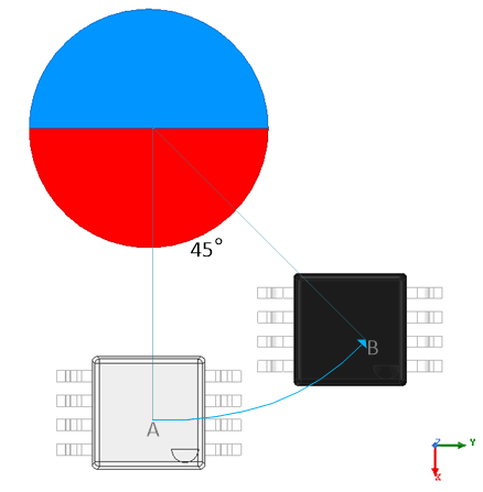
A sensor that is not aligned towards the center of a rotating magnet will separate the B-Field vector differently than shown in Figure 2-2. For instance, consider the alignment shown in Figure 3-1 with the sensor in-plane to the magnet.
 Figure 3-1 In-Plane Sensor With 45°
Rotation
Figure 3-1 In-Plane Sensor With 45°
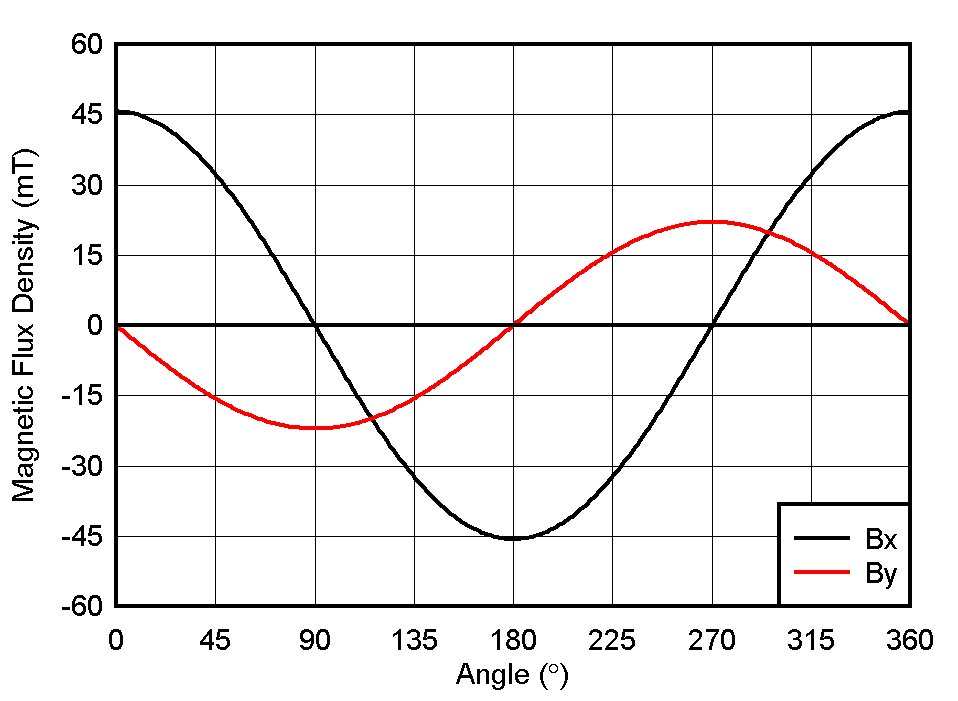
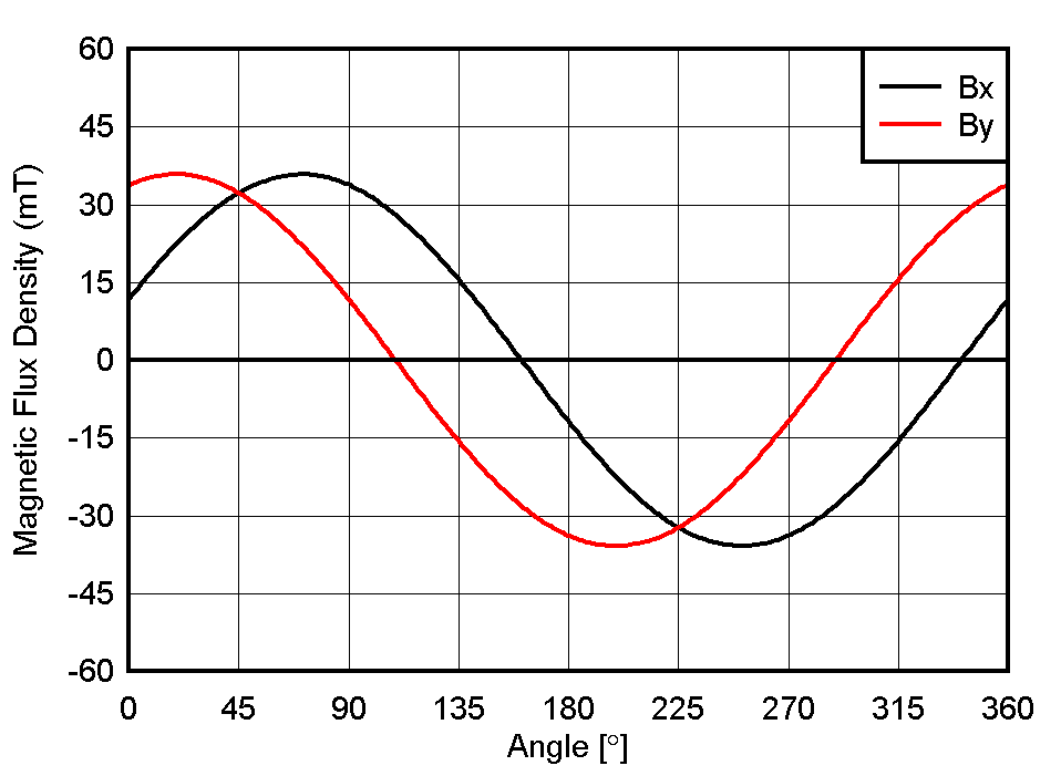
RotationIn this case, the sensor is at the 45° position, but is still aligned the same as when it was placed along the X axis. At 45° rotation of the magnet, the magnet pole is aimed at the sensor, but is not directly orthogonal to any element within the device. This can also be achieved by rotating the sensor in place by 45°. Mechanically, both orientations will produce the same effect. As a result of this rotation, we can observe the expected change to the magnetic field inputs in both positions A and B as shown in Figure 3-2.

 Figure 3-2 In-Plane Alignment with 45°
Rotation
Figure 3-2 In-Plane Alignment with 45°
RotationBy rotating the sensor we have achieved matched inputs in each component of B-field vector. With the magnet rotated 45°, and with the pole directed towards the sensor, each Hall element will be matched relative to the X and Y components of the B-field vector and will detect magnitudes that are equal. With this rotation, each sensor is able to detect a peak value equivalent to the average of the original X and Y components of the B-Field vector. As a result, this orientation provides an ideal alignment of the magnet and sensor for In-Plane detection.