SLAA957 September 2020 MSP430AFE221 , MSP430AFE222 , MSP430AFE223 , MSP430AFE231 , MSP430AFE232 , MSP430AFE233 , MSP430AFE251 , MSP430AFE252 , MSP430AFE253 , MSP430F2003 , MSP430F2013 , MSP430F2013-EP , MSP430F423A , MSP430F4250 , MSP430F425A , MSP430F4260 , MSP430F4270 , MSP430F427A , MSP430F47126 , MSP430F47127 , MSP430F47163 , MSP430F47166 , MSP430F47167 , MSP430F47173 , MSP430F47176 , MSP430F47177 , MSP430F47183 , MSP430F47186 , MSP430F47187 , MSP430F47193 , MSP430F47196 , MSP430F47197 , MSP430F477 , MSP430F478 , MSP430F4783 , MSP430F4784 , MSP430F479 , MSP430F4793 , MSP430F4794 , MSP430F6720 , MSP430F6720A , MSP430F6721 , MSP430F6721A , MSP430F6723 , MSP430F6723A , MSP430F6724 , MSP430F6724A , MSP430F6725 , MSP430F6725A , MSP430F6726 , MSP430F6726A , MSP430F6730 , MSP430F6730A , MSP430F6731 , MSP430F6731A , MSP430F6733 , MSP430F6733A , MSP430F6734 , MSP430F6734A , MSP430F6735 , MSP430F6735A , MSP430F6736 , MSP430F6736A , MSP430F6745 , MSP430F67451 , MSP430F67451A , MSP430F6745A , MSP430F6746 , MSP430F67461 , MSP430F67461A , MSP430F6746A , MSP430F6747 , MSP430F67471 , MSP430F67471A , MSP430F6747A , MSP430F6748 , MSP430F67481 , MSP430F67481A , MSP430F6748A , MSP430F6749 , MSP430F67491 , MSP430F67491A , MSP430F6749A , MSP430F67621 , MSP430F67621A , MSP430F67641 , MSP430F67641A , MSP430F6765 , MSP430F67651 , MSP430F67651A , MSP430F6765A , MSP430F6766 , MSP430F67661 , MSP430F67661A , MSP430F6766A , MSP430F6767 , MSP430F67671 , MSP430F67671A , MSP430F6767A , MSP430F6768 , MSP430F67681 , MSP430F67681A , MSP430F6768A , MSP430F6769 , MSP430F67691 , MSP430F67691A , MSP430F6769A , MSP430F6775 , MSP430F67751 , MSP430F67751A , MSP430F6775A , MSP430F6776 , MSP430F67761 , MSP430F67761A , MSP430F6776A , MSP430F6777 , MSP430F67771 , MSP430F67771A , MSP430F6777A , MSP430F6778 , MSP430F67781 , MSP430F67781A , MSP430F6778A , MSP430F6779 , MSP430F67791 , MSP430F67791A , MSP430F6779A , MSP430FE423 , MSP430FE4232 , MSP430FE423A , MSP430FE4242 , MSP430FE425 , MSP430FE4252 , MSP430FE425A , MSP430FE427 , MSP430FE4272 , MSP430FE427A , MSP430FG4250 , MSP430FG4260 , MSP430FG4270 , MSP430FG477 , MSP430FG478 , MSP430FG479 , MSP430FG6425 , MSP430FG6426 , MSP430FG6625 , MSP430FG6626 , MSP430FR5041 , MSP430FR5043 , MSP430FR50431 , MSP430FR6005 , MSP430FR6007 , MSP430FR6041 , MSP430FR6043 , MSP430FR60431 , MSP430FR6045 , MSP430FR6047 , MSP430FR60471 , MSP430I2020 , MSP430I2021 , MSP430I2030 , MSP430I2031 , MSP430I2040 , MSP430I2041
- Abstract
- Trademarks
- 1Introduction: MSP Sigma-Delta ADCs and Common Applications
- 2MSP Sigma-Delta ADC Portfolio
- 3Sigma-Delta ADC Overview
-
4MSP Sigma-Delta ADC Features
- 4.1 ADC Inputs: Differential or Single-Ended
- 4.2 Input Channels: Independent or Multiplexed
- 4.3 Integrated Buffers
- 4.4 Integrated PGAs
- 4.5 Offset Calibration: Internal or External
- 4.6 Voltage Reference: Internal or External
- 4.7 ADC Modulator Clock Frequency: Fixed or Adjustable
- 4.8 Sampling Rate versus Data Rate
- 4.9 Conversion Mode: Single or Continuous
- 4.10 Groups of ADC Channels
- 4.11 Preload
- 4.12 Output Format: Unipolar or Bipolar Data
- 4.13 Module Synchronization
- 4.14 Architecture: Discrete-Time versus Continuous-Time
- 5Solutions to Common MSP Sigma-Delta ADC Configuration Issues
- 6Frequently Asked Questions
- 7References
6 Frequently Asked Questions
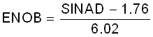
How do I calculate the effective number of bits (ENOB)?
For AC inputs, the ENOB can be calculated using Equation 5 and the SINAD values provided in the device-specific data sheet. For DC inputs, the ENOB equivalent is called the effective resolution and is not provided in the data sheet. The effective resolution can be calculated using the standard deviation from several samples of a known DC input. Other important performance parameters for DC inputs include integral nonlinearity (INL) and differential nonlinearity (DNL). For more details about the effective resolution, see the A bone of contention: ENOB or effective resolution? blog.
Why can't I find the Sigma-Delta ADC sampling frequency in the data sheet?
The sampling frequency is typically not provided because it depends on the modulator frequency and the OSR. For some SD ADC modules, the modulator frequency and OSR are adjustable, so a pair of modulator frequency and OSR combinations can result in the same sampling frequency with different performance.
Can I use the differential ADC inputs as a single-ended ADC input?
Yes, but remember that this configuration halves the dynamic range. To learn more about dynamic range, see A Glossary of Analog-to-Digital Specifications and Performance Characteristics.
What's the difference between common-mode and differential input voltages?
Common-mode means the same voltage is applied to both the positive and negative ADC pins. In this case, the differential voltage would be zero (ignoring any noise or offsets) because there's no voltage difference between the pins. Common-mode and differential inputs can be applied simultaneously. For example, a DC bias could be applied to both pins while an AC signal is applied between the pins. See the device-specific data sheet for the absolute maximum ratings.
What type of decimation filter is used?
The SD ADC modules in Table 2-1 except SDHS feature second-order modulators and third-order (SINC3) decimation filters (also referred to as comb filters due to the shape of their frequency response). The SDHS module features a third-order modulator and multi-stage CIC decimation filters. To learn more about decimation filters, see Digital Filter Types in Delta-Sigma ADCs and the device-specific user's guide.
What does the frequency response of the decimation filter in the user's guide tell me?
The frequency response in the device-specific user's guide illustrates the level of attenuation at various input frequencies. Notches attenuate the input signal completely and occur at multiples of the sampling frequency (data rate). Typically, the minimum sampling frequency is based on the Nyquist rate, but a higher sampling frequency can be used to shift the first notch and reduce the roll-off attenuation of the input signal. Increasing the sampling frequency may reduce performance due to a lower OSR and will capture more harmonic content which may be desirable or not depending on the application. To learn more about roll-off attenuation, read the Quantifying harmonic distortion - Effect of sinc3 filter roll off blog.
If you decide to use a discrete ADC in your design, remember that some ADCs feature decimation filters with notches at 50 or 60 Hz to intentionally filter out noise from power supplies sourced by AC mains, so those ADCs should not be used in metering applications to measure AC power or energy.
Can I use external modulators with the internal decimation filters?
Yes, the SD24_B module supports external modulators. To learn more about this configuration, see the Multi-phase Energy Measurement with Isolated Shunt Sensors Reference Design (TIDA-00601).