SLVA720A July 2015 – October 2020 CD14538B , CD14538B-MIL , CD4047B , CD4047B-MIL , CD4098B , CD4098B-MIL , CD54HC123 , CD54HC221 , CD54HC4538 , CD54HCT123 , CD54HCT4538 , CD74HC123 , CD74HC221 , CD74HC423 , CD74HC4538 , CD74HC4538-Q1 , CD74HCT123 , CD74HCT221 , CD74HCT423 , CD74HCT4538 , SN54121 , SN54123 , SN54221 , SN54AHC123A , SN54AHCT123A , SN54LS123 , SN54LS123-SP , SN54LS221 , SN74121 , SN74221 , SN74AHC123A , SN74AHC123A-EP , SN74AHCT123A , SN74LS122 , SN74LS123 , SN74LS221 , SN74LS423 , SN74LV123A , SN74LV123A-EP , SN74LV123A-Q1 , SN74LV221A , SN74LV221A-Q1 , SN74LVC1G123
- 1Introduction
- 2Terminology
- 3Theory of Operation
- 4Applications
-
5Frequently Asked Questions
- 5.1 How do I calculate the output pulse length?
- 5.2 How do I configure the SN74LVC1G123's inputs for ______ edge triggering?
- 5.3 How stable is the output pulse length over VCC changes?
- 5.4 How stable is the output pulse length over temperature changes?
- 5.5 Which inputs of the SN74LVC1G123 have Schmitt-triggers?
- 5.6 Can I connect the Cext pin to ground?
- 6Revision History
3.2 Operation
- Trigger event occurs. This can be a rising or falling edge depending on the configuration.
- Cext is discharged very quickly and is allowed to charge through the external RC network.
- Output switches to the unstable state when the capacitor voltage drops below the designed threshold voltage. It returns to the stable state when the capacitor voltage charges back up above the threshold voltage.
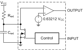
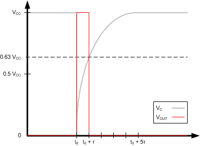
The circuit representing this operation is shown in Figure 3-1, and the capacitor voltage plotted with the output voltage is shown in Figure 3-2. This plot is simulated from an ideal system designed to switch the output when the capacitor voltage is 63.2% of its full charge.
 Figure 3-1 Functional Diagram of a Monostable Multivibrator
 Figure 3-2 Capacitor Voltage With Aligned Output Pulse (Ideal)
The schematic shown in Figure 3-1 is a simplified version of the internal operation of the SN74LVC1G123, but it does not capture all of the nuances of operating a monostable multivibrator. In this schematic, it is assumed that temperature and supply voltage will not change the output of the circuit, and that the RC circuit will always have a sufficient charge and discharge path for operation. It is additionally assumed that there is enough time for the system to recover between output pulses.
While the system is at rest, the capacitor is fully charged and the output voltage is LOW. When a trigger event occurs, the external capacitor, Cext, is quickly discharged through the MOSFET, and then is allowed to charge through the external resistor, Rext. When the capacitor voltage initially drops below the reference voltage, 0.63212 VCC, the comparator output immediately changes to HIGH. The output then remains HIGH until the capacitor charges up enough to surpass 0.63212 VCC, when it returns to its stable LOW state. Since it takes approximately one time constant to 0.63212 VCC, the output pulse will be very close to τ = R × C in length. In a real monostable multivibrator, such as the SN74LVC1G123, the output pulse length will also be dependent on the supply voltage and the capacitor size. These two dependencies are usually represented as a multiplier, K. Equation 2 shows the general pulse width (tw) equation.
The SN74LVC1G123 is a retriggering monostable multivibrator. This means that each trigger event produces an output of the chosen length. If the output is already outputting a pulse when the trigger occurs, then the output will continue to output as shown in Figure 3-3. The timing diagram in Figure 3-3 shows the difference between a retriggerable and non-retriggerable monostable multivibrator when both have the same pulse width.
 Figure 3-3 Difference Between Retriggerable and Non-Retriggerable Monostable Multivibrators