SLVAFF1 January 2023 DRV8452 , DRV8462
PRODUCTION DATA
- Abstract
- Trademarks
- 1Power Efficiency of Stepper Motor Drivers
-
2Auto-Torque
- 2.1 Auto-Torque: Learning Principle
- 2.2 Current Control
- 2.3 PD Control Loop
- 2.4
Impact of Auto-Torque Tuning
Parameters
- 2.4.1 Impact of Learning Parameters on Load Transient Response
- 2.4.2 Impact of ATQ_UL, ATQ_LL Hysteresis
- 2.4.3 Impact of Load Profile on Power Saving
- 2.4.4 Adaptive ATQ_UL, ATQ_LL
- 2.4.5 PD Parameter Dependency Curves
- 2.4.6 ATQ_CNT at Different Motor Speeds
- 2.4.7 ATQ_CNT at Different Supply Voltages
- 2.4.8 Motor Temperature Estimation
- 2.5 Efficiency Improvement With Auto-Torque
- 3Case Studies
- 4Summary
- 5References
2.1.1 Configuring Auto-Torque Learning Routine
After auto-torque algorithm is enabled, the learning routine must be run to estimate the ATQ_LRN parameters.
The learning routine uses the linear relation between ATQ_LRN and motor current described in Equation 3. You have to select two current values at which learning will be performed, with no load torque applied on the motor. These two current values are programmed by the ATQ_LRN_MIN_CURRENT and ATQ_LRN_STEP registers.
- Initial current level = ATQ_LRN_MIN_CURRENT x 8
- Final current level = Initial current level + ATQ_LRN_STEP
The ATQ_LRN values at these two currents are saved in the ATQ_LRN_CONST1 and ATQ_LRN_CONST2 registers. These two registers are used to interpolate ATQ_LRN value for all other currents within the operating range of the application.
Table 2-1 lists the registers associated with auto-torque learning routine.
| Register Name | Description |
|---|---|
| ATQ_LRN_MIN_CURRENT[4:0] | Represents the initial current level for auto-torque learning routine. |
| ATQ_LRN_STEP[1:0] | Represents the increment to initial current level. It supports four
options:
Example : If ATQ_LRN_STEP = 10b and ATQ_LRN_MIN_CURRENT = 11000b, then:
|
| ATQ_LRN_CYCLE_SELECT[1:0] | Represents the number of electrical half cycles spent in one
current level after which the learning routine allows the current to
jump to the other level. It supports four options:
|
| LRN_START | Writing 1b to this bit enables the auto-torque learning routine. After learning is completed, this bit automatically goes to 0b. |
| LRN_DONE | This bit becomes 1b after learning is complete. |
| ATQ_LRN_CONST1[10:0] | Indicates the ATQ_LRN parameter at the initial learning current level. |
| ATQ_LRN_CONST2[10:0] | Indicates the ATQ_LRN parameter at the final learning current level. |
| VM_SCALE | When this bit is 1b, the auto-torque algorithm automatically adjusts the ATQ_UL, ATQ_LL and ATQ_LRN parameters as per the supply voltage variation. |
Here are few points to consider while setting up the learning routine parameters:
- It is recommended to select the initial current level between 30% to 50% of the maximum operating current.
- Final current level must not exceed 255 and can be selected between 80% and 100% of the maximum operating current.
- Current waveform distortions (due to high speed or low supply voltage) can cause incorrect reading of the ATQ_LRN parameters. The learning current levels should be chosen away from the currents where waveform distortions are observed.
- Low values of ATQ_LRN_CYCLE_SELECT result in quicker learning. However, in systems prone to noise, higher ATQ_LRN_CYCLE_SELECT can result in more stable ATQ_LRN parameter values.
- Learning should be done after the motor attains the steady-state speed.
- Re-learning should be done if the motor is changed, or the motor speed changes by ± 10%.
For a quick summary, the following sequence of commands should be applied to enable automatic learning:
- Write 1b to ATQ_EN.
- Run the motor with no load.
- Program ATQ_LRN_MIN_CURRENT.
- Program ATQ_LRN_STEP.
- Program ATQ_LRN_CYCLE_SELECT.
- Write 1b to ATQ_LRN_START.
- The algorithm runs the motor with initial current level for ATQ_LRN_CYCLE_SELECT number of electrical half cycles.
- Next, the algorithm runs the motor with final current level for ATQ_LRN_CYCLE_SELECT number of electrical half cycles.
- After learning is complete:
- ATQ_LRN_START bit is auto cleared to 0b
- ATQ_LRN_DONE bit becomes 1b
- ATQ_LRN_CONST1 and ATQ_LRN_CONST2 are populated in their respective registers
- Motor current goes to ATQ_TRQ_MAX
Once the ATQ_LRN_CONST1 and ATQ_LRN_CONST2 are known from the prototyping tests, they can be used for mass production without invoking the learning routine again. The following sequence of commands should be applied in mass production:
- VREF set to the same value as during learning in prototype tests
- Program ATQ_LRN_MIN_CURRENT
- Program ATQ_LRN_STEP
- Program ATQ_LRN_CONST1
- Program ATQ_LRN_CONST2
- Write 1b to ATQ_EN
Figure 2-3 shows the consolidated flowchart of the auto-torque learning routine.
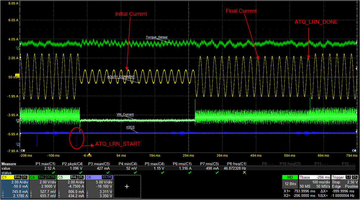
 Figure 2-4 Auto-Torque Learning
Traces from top to bottom: load torque, coil current, supply current, nSCS.
Figure 2-4 shows an automatic learning process with 740 mA initial current (IFS1) and 2.2 A final current (IFS2). The ATQ_LEARN_CYCLE_SELECT corresponds to 32 half-cycles.