SNAU266A July 2021 – August 2022
B USB2ANY Firmware Upgrade
When the onboard USB2ANY programmer is first connected, or if the firmware revision used for the onboard USB2ANY programmer does not match the version used by TICS Pro (2.7.0.0), TICS Pro will request a firmware update. Follow the pop-up instructions to complete the update.
- When the USB2ANY Firmware Requirement pop-up window appears, click
OK to continue.
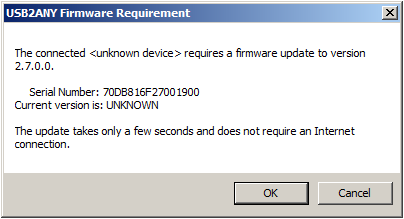 Figure B-1 Firmware
Requirement
 - The Figure B-2
pop-up window will load. Disconnect the USB cable from the EVM.
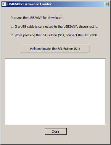 Figure B-2 Firmware
Loader
 - While pressing the BSL button (shown below), connect the USB2ANY cable.
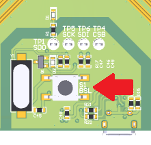 Figure B-3 BSL Button Location
 - The firmware loader should recognize the USB2ANY as
a target for programming, and an Figure B-4 button
should appear.
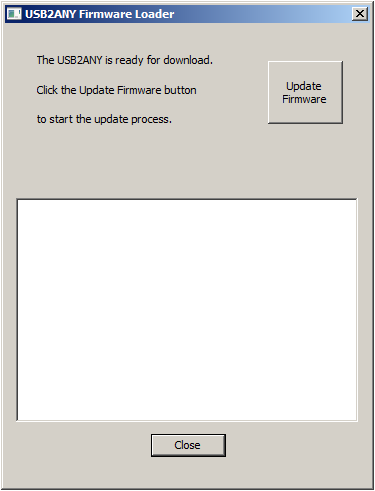 Figure B-4 Update
Firmware
 - Click Upgrade Firmware to start the firmware upgrade. Click
Close after the upgrade is complete.
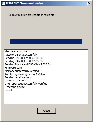 Figure B-5 Firmware Update
Complete
 - Go to USB communications → Interface in
the TICS Pro software to check the USB connection. Make sure the USB
Connected button is green.
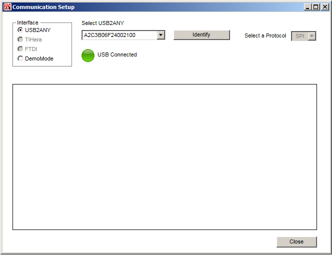 Figure B-6 USB
Communications