SNVA951 November 2020 LM61460-Q1 , LM63615-Q1 , LM63625-Q1 , LM63635-Q1 , LMR33620-Q1 , LMR33630-Q1
8.1 Thermal Camera
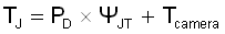
Probably the most convenient and reliable way to measure junction temperature is to use a thermal camera. These devices can be expensive, but they give a wide view of the temperature on the PCB, not just of the regulator. This can be helpful when evaluating a new design for "hot-spot" regions on the PCB. The simple IR-type thermal probes can also be useful, but they only give one temperature and are not as accurate as the cameras. It should be remembered that these instruments display the surface temperature of a device. The surface temperature is converted to junction temperature using Equation 6.
These cameras usually assume a certain thermal emissivity for the object they are measuring. Some components (or exposed copper) can be somewhat reflective and may give a misleading temperature reading. Since IC packages exhibit a dull black color, the camera can take an accurate temperature reading without any modification of the device.