SPRUI78D March 2019 – January 2022 TMS320F28075 , TMS320F28075-Q1 , TMS320F28076 , TMS320F28374D , TMS320F28374S , TMS320F28375D , TMS320F28375S , TMS320F28375S-Q1 , TMS320F28376D , TMS320F28376S , TMS320F28377D , TMS320F28377D-Q1 , TMS320F28377S , TMS320F28377S-Q1 , TMS320F28378D , TMS320F28378S , TMS320F28379D , TMS320F28379D-Q1 , TMS320F28379S
- Trademarks
- 1 Introduction
- 2 System Integrator Development Interface Agreement
- 3 C2000 Development Process for Management of Systematic Faults
- 4 TMS320F2837xD/S and TMS320F2807x MCU Architecture for Management of Random Faults
- 5 Brief Description of Safety Elements
-
6 Brief Description of Diagnostics
- 6.1
C2000 MCU Infrastructure Components
- 6.1.1 Clock Integrity Check Using CPU Timer
- 6.1.2 Clock Integrity Check Using HRPWM
- 6.1.3 EALLOW and MEALLOW Protection for Critical Registers
- 6.1.4 Efuse Autoload Self-Test
- 6.1.5 Efuse ECC
- 6.1.6 Efuse ECC Logic Self-Test
- 6.1.7 External Clock Monitoring via XCLKOUT
- 6.1.8 External Monitoring of Warm Reset (XRSn)
- 6.1.9 External Voltage Supervisor
- 6.1.10 External Watchdog
- 6.1.11 Glitch Filtering on Reset Pins
- 6.1.12 Hardware Disable of JTAG Port
- 6.1.13 Internal Watchdog (WD)
- 6.1.14 Lock Mechanism for Control Registers
- 6.1.15 Missing Clock Detect (MCD)
- 6.1.16 NMIWD Reset Functionality
- 6.1.17 NMIWD Shadow Registers
- 6.1.18 Multi-Bit Enable Keys for Control Registers
- 6.1.19 Online Monitoring of Temperature
- 6.1.20 Periodic Software Read Back of Static Configuration Registers
- 6.1.21 Peripheral Clock Gating (PCLKCR)
- 6.1.22 Peripheral Soft Reset (SOFTPRES)
- 6.1.23 PLL Lock Profiling Using On-Chip Timer
- 6.1.24 Reset Cause Information
- 6.1.25 Software Read Back of Written Configuration
- 6.1.26 Software Test of ERRORSTS Functionality
- 6.1.27 Software Test of Missing Clock Detect Functionality
- 6.1.28 Software Test of Reset
- 6.1.29 Software Test of Watchdog(WD) Operation
- 6.2
Processing Elements
- 6.2.1 CLA Handling of Illegal Operation and Illegal Results
- 6.2.2 CLA Liveness Check Using CPU
- 6.2.3 CPU Hardware Built-In Self-Test (HWBIST)
- 6.2.4 CPU Hardware Built-In Self-Test (HWBIST) Auto-Coverage
- 6.2.5 CPU Hardware Built-In Self-Test (HWBIST) Fault Injection Capability
- 6.2.6 CPU Hardware Built-In Self-Test (HWBIST) Timeout Feature
- 6.2.7 CPU Handling of Illegal Operation, Illegal Results and Instruction Trapping
- 6.2.8 Reciprocal Comparison by Software
- 6.2.9 Software Test of CLA
- 6.2.10 Stack Overflow Detection
- 6.2.11 VCU CRC Check of Static Memory Contents
- 6.2.12 VCU CRC Auto Coverage
- 6.2.13 Disabling of Unused CLA Task Trigger Sources
- 6.3
Memory (Flash, SRAM and ROM)
- 6.3.1 Bit Multiplexing in Flash Memory Array
- 6.3.2 Bit Multiplexing in SRAM Memory Array
- 6.3.3 Data Scrubbing to Detect/Correct Memory Errors
- 6.3.4 Flash ECC
- 6.3.5 Flash Program Verify and Erase Verify Check
- 6.3.6 Software Test of ECC Logic
- 6.3.7 Software Test of Flash Prefetch, Data Cache and Wait-States
- 6.3.8 Access Protection Mechanism for Memories
- 6.3.9 SRAM ECC
- 6.3.10 SRAM Parity
- 6.3.11 Software Test of Parity Logic
- 6.3.12 Software Test of SRAM
- 6.4
On-Chip Communication Including Bus-Arbitration
- 6.4.1 1oo2 Software Voting Using Secondary Free Running Counter
- 6.4.2 DMA Overflow Interrupt
- 6.4.3 Event Timestamping Using IPC Counter
- 6.4.4 Maintaining Interrupt Handler for Unused Interrupts
- 6.4.5 Majority Voting and Error Detection of Link Pointer
- 6.4.6 PIE Double SRAM Comparison Check
- 6.4.7 PIE Double SRAM Hardware Comparison
- 6.4.8 Power-Up Pre-Operational Security Checks
- 6.4.9 Software Check of X-BAR Flag
- 6.4.10 Software Test of ePIE Operation Including Error Tests
- 6.4.11 Disabling of Unused DMA Trigger Sources
- 6.4.12 IPC 64-Bit Counter Value Plausibility Check
- 6.5
Digital I/O
- 6.5.1 ECAP Application Level Safety Mechanism
- 6.5.2 ePWM Application Level Safety Mechanism
- 6.5.3 ePWM Fault Detection Using XBAR
- 6.5.4 ePWM Synchronization Check
- 6.5.5 eQEP Application Level Safety Mechanisms
- 6.5.6 eQEP Quadrature Watchdog
- 6.5.7 eQEP Software Test of Quadrature Watchdog Functionality
- 6.5.8 Hardware Redundancy
- 6.5.9 HRPWM Built-In Self-Check and Diagnostic Capabilities
- 6.5.10 Information Redundancy Techniques
- 6.5.11 Monitoring of ePWM by eCAP
- 6.5.12 Monitoring of ePWM by ADC
- 6.5.13 Online Monitoring of Interrupts and Events
- 6.5.14 SDFM Comparator Filter for Online Monitoring
- 6.5.15 SD Modulator Clock Fail Detection Mechanism
- 6.5.16 Software Test of Function Including Error Tests
- 6.6
Analogue I/O
- 6.6.1 ADC Information Redundancy Techniques
- 6.6.2 ADC Input Signal Integrity Check
- 6.6.3 ADC Signal Quality Check by Varying Acquisition Window
- 6.6.4 CMPSS Ramp Generator Functionality Check
- 6.6.5 DAC to ADC Loopback Check
- 6.6.6 DAC to Comparator Loopback Check
- 6.6.7 Opens/Shorts Detection Circuit for ADC
- 6.6.8 VDAC Conversion by ADC
- 6.6.9 Disabling Unused Sources of SOC Inputs to ADC
- 6.7
Data Transmission
- 6.7.1 Bit Error Detection
- 6.7.2 CRC in Message
- 6.7.3 DCAN Acknowledge Error Detection
- 6.7.4 DCAN Form Error Detection
- 6.7.5 DCAN Stuff Error Detection
- 6.7.6 EMIF Access Latency Profiling Using On-Chip Timer
- 6.7.7 EMIF Access Protection Mechanism
- 6.7.8 EMIF Asynchronous Memory Timeout Protection Mechanism
- 6.7.9 I2C Access Latency Profiling Using On-Chip Timer
- 6.7.10 Information Redundancy Techniques Including End-to-End Safeing
- 6.7.11 I2C Data Acknowledge Check
- 6.7.12 McBSP Receiver Overrun Detection
- 6.7.13 McBSP Receiver Sync Error Detection
- 6.7.14 McBSP Transmitter Sync Error Detection
- 6.7.15 McBSP Transmitter Underflow Detection
- 6.7.16 Parity in Message
- 6.7.17 SCI Break Error Detection
- 6.7.18 SCI Frame Error Detection
- 6.7.19 SCI Overrun Error Detection
- 6.7.20 Software Test of Function Using I/O Loopback
- 6.7.21 SPI Data Overrun Detection
- 6.7.22 Transmission Redundancy
- 6.1
C2000 MCU Infrastructure Components
- 7 Safety Architecture Configurations
- 8 Terms and Definitions
- 9 Summary of Safety Features and Diagnostics
- 10References
- 11Revision History
7 Safety Architecture Configurations
The various redundancy architectures possible for the safety instrumented systems are indicated in Table 7-1. For more information, see [10].
Table 7-1 Safety Architecture
Configurations
| Diagnostic Implementation | ||
|---|---|---|
| 1 | 1oo1 Architecture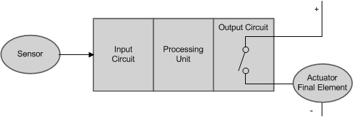 |
NA |
| 2 | 1oo1D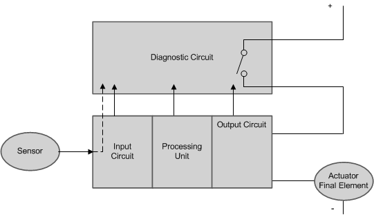 |
Diagnostic channel is implemented using various hardware diagnostic features like Watchdog, and so forth. |
| 3 | 1oo1D Same figure as above. |
Diagnostic channel is implemented using reciprocal comparison (uses two processing units for implementing reciprocal comparison) and other hardware diagnostic features. |
| 4 | 1oo2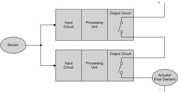 |
Two different processing units are used to implement one channel. |
| 5 | 2oo2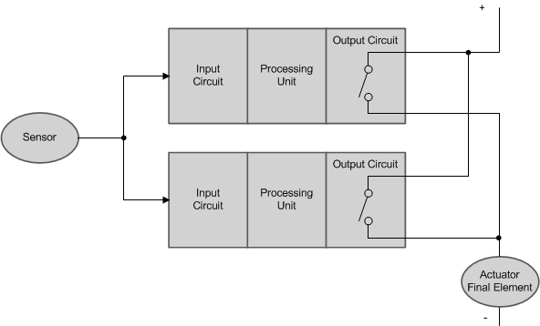 |
Two different processing units are used to implement one channel. |
| 6 | 2oo2D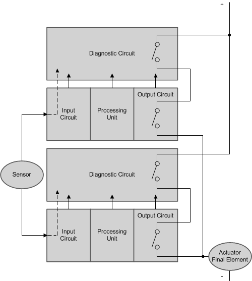 |
Two 1oo1D structures of #2 wired together to implement a safe channel. |
| 7 | 2oo2D Same figure as above. |
Two 1oo1D structures of #3 wired together. |
| 8 | 1oo2D |
Similar to 2oo2D implementation of #6 with additional control lines wired to control one set of units using the other unit |
| 9 | 1oo2D Same figure as above. |
Similar to 2oo2D implementation of #7 with additional control lines wired to control one set of units using the other unit. |
| 10 | 2oo3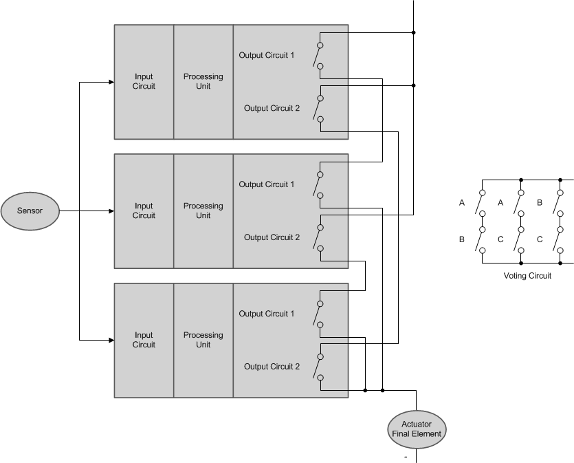 |
Use three different processing units to implement majority voting. The fourth channel can be used either standalone or with hardware diagnostic features. |