SPRUIT1B May 2020 – November 2020
- Trademarks
- 1Introduction
- 2GESI Expansion Board Overview
- 3GESI Expansion Board - User Setup/Configuration
- 4GESI Expansion Board Hardware Architecture
- A Interface Mapping
- B GESI Board GPIO Mapping
- C I2C Address Mapping
- D Revision History
4.4 Ethernet Interface
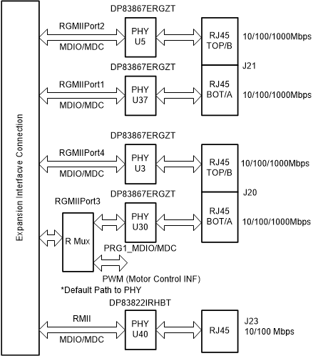
The Jacinto7 EVM – GESI Expansion board provides an option to the users to validate the Jacinto7 SoC’s RGMII and RMII controllers.
GESI supports 4 RGMII interfaces using Four DP83867 Gigabit Ethernet. It is connected to 2x stacked RJ45 connector J20A & J20B and J21A & J21B. Default Configurations of these PHYs can be determined by Resistor Straps on configuration pins of PHY.
| Ports | RGMII Port1 | RGMII Port2 | RGMII Port3 | RGMII Port4 |
|---|---|---|---|---|
| Connectors | J21A | J21B | J20A | J20B |
| PHY Address | 00000 | 00011 | 01100 | 01111 |
| Auto Negotiation | Enabled | Enabled | Enabled | Enabled |
| ANEGSel | 10/100/1000 | 10/100/1000 | 10/100/1000 | 10/100/1000 |
| RGMII Clock Skew TX | 0 ns | 0 ns | 0 ns | 0 ns |
| RGMII Clock Skew RX | 2 ns | 2 ns | 2 ns | 2 ns |
On these RGMII PHYs either CPSWxG or Main domain RGMII interface of Jacinto7 processor can be validated by software configuration. It is specific to the processor.
 Figure 4-3 Ethernet Interface
Ethernet PHY management bus, MDIO-MDC is wired through 2:1 mux SN74CB3Q3257PWR. For Mux selection GPIO details, see Section B.
RMII connection of DP83822IRHBT provides a 10/100 Mbps port (J23).