SWRA729 April 2022 CC1352P , CC1354P10 , CC2652P
1 Reference Designs Available
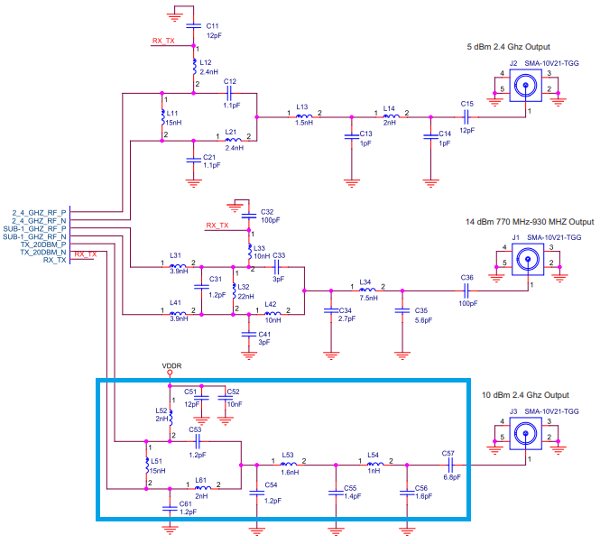
The existing reference designs for the 10 dBm PA 2.4 GHz are based upon LAUNCHXL-CC2652P [7] and LAUNCHXL-CC1352P-4 [6], these are based upon passive discrete components, refer to Figure 1-1.
Each RF port is terminated with 50-ohm impedance that can be connected to SMA connector, switch or diplexer. The main advantage in using a switch or diplexer is a common RF port instead of several RF ports.
LAUNCHXL-CC2652P [4] has two RF ports and LAUNCHXL-CC1352P-4 [5] has three RF ports. The additional RF port in CC1352P can be configured for both Sub-1 GHz or 2.4 GHz. The PA port of CC2652P [1] and CC1352P [2] can be configured as 20 dBm or 10 dBm. The PA IPC [3] can be used for 10 dBm, 2.4 GHz for both CC26x2P [1] and CC1352P [2]
This application note will document the measurements performed on the PA Tx port for CC2652P [1] and CC1352P [2] for 10 dBm 2.4 GHz with the IPC [3] component. The parts in the reference design not related to the PA port will not be discussed.
A switch (SPDT for CC2652P and SP3T for CC1352P) is used on the LaunchPads [5] to enable a common RF port which is connected to an integrated PCB dual-band antenna.
 Figure 1-1 CC1352PEM-XD7793-XD24-PA24_10 dBm RF Section Schematic