SWRA734 December 2021 CC1312PSIP , CC1312R , CC1312R7 , CC1314R10 , CC1352P , CC1352P7 , CC1352R , CC1354P10 , CC1354R10 , CC2652P , CC2652P7 , CC2652R , CC2652RB , CC2652RSIP
6.1 PAN Coordinator Switching Due to Sync Loss
For this particular scenario, it is enough to modify the application layer of the sensor device for a basic implementation of PAN coordinator switching.
- Import the following example projects into the IDE workspace:
- TI 15.4-Stack Sensor project
- TI 15.4-Stack Collector project (used as original collector)
- TI 15.4-Stack Collector project (used as replacement collector)
Note: To differentiate the collectors when using the Common User Interface (CUI), modify the SFF_MENU_TITLE macro in csf.c, so that each project is properly identified. It may also be necessary to rename the projects. - Configure the sensor and collector projects so that they operate in the same mode, and with the same PHY. Also consider the following:
- The PAN ID field for the sensor should be set as 0xFFFF.
- Each collector device should use a different PAN ID.
- Each collector device should use a different channel mask.
- The sensor device should use a channel mask that covers the channels at which both collectors operate.
- Use different short addresses for each coordinator. The short address can be modified in the file advanced_config.h.
- Choose an appropriate value for the Orphan Back-off Interval in the Sysconfig configuration for the sensor (for example 5000 ms).
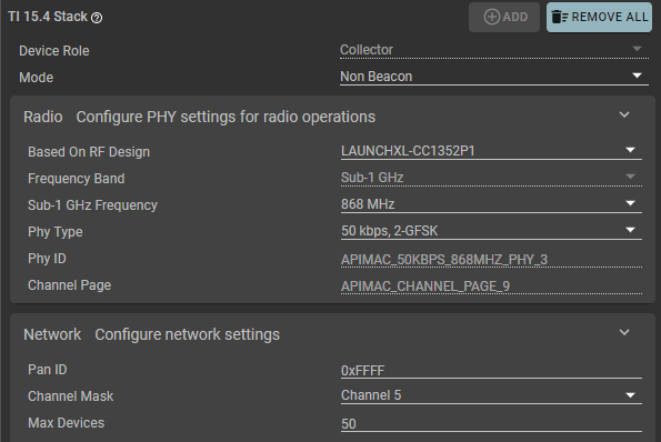 Figure 6-2 TI 15.4-Stack SysConfig Configuration for First Collector Device
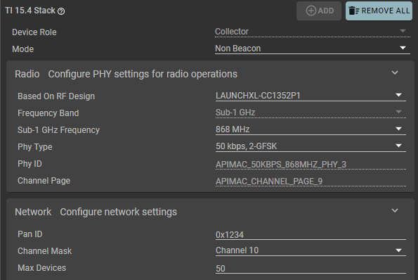 Figure 6-3 TI 15.4-Stack SysConfig Configuration for Second Collector Device
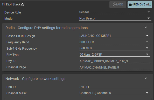 Figure 6-4 TI 15.4-Stack SysConfig Configuration for Sensor Device
 - Build the collector projects and flash the LaunchPad kits.
- Open the file jdllc.c in the sensor project, and add a local function prototype of the function that will be used to perform the network disassociation.
static void abandonNetwork(void); - In jdllc.c in the sensor project, add the following lines in the section for constants and definitions:
/* Maximum score used to evaluate a channel when looking for second coordinator */
#define JDLLC_MAX_ENERGY             		255
#define JDDLC_MAX_RECONNECTION_ATTEMPTS		5
The first macro definition is used as a starting point for the energy detect scans that the sensor device must execute. And the second macro definition indicates the number of times the sensor will attempt to reconnect to its original PAN coordinator before switching to a different PAN coordinator.
- In jdllc.c, define the local function used to perform the network disassociation.
void abandonNetwork(void)
{
    /* stop polling */
    if(!CONFIG_RX_ON_IDLE)
    {
        Ssf_setPollClock(0);
    }

    /* enable looking for new parent */
    parentFound = false;

    /* set devInfoBlock back to defaults */
    devInfoBlock.panID = CONFIG_PAN_ID;
    devInfoBlock.channel = JDLLC_INVALID_CHANNEL;

    if(!CONFIG_FH_ENABLE)
    {
      devInfoBlock.coordShortAddr = 0xFFFF;
    }
    else
    {
      devInfoBlock.coordShortAddr = FH_COORD_SHORT_ADDR;
    }

#ifdef FEATURE_MAC_SECURITY
    ApiMac_secDeleteDevice(&devInfoBlock.devExtAddr);
#endif

    /* Reset devInfoBlock to default values */
    memset(&devInfoBlock.coordExtAddr[0], 0x00, APIMAC_SADDR_EXT_LEN);
    devInfoBlock.devShortAddr = 0xFFFF;
    memset(&devInfoBlock.devExtAddr[0], 0x00, APIMAC_SADDR_EXT_LEN);
    devInfoBlock.beaconOrder = CONFIG_MAC_BEACON_ORDER;
    devInfoBlock.superframeOrder = CONFIG_MAC_SUPERFRAME_ORDER;
    devInfoBlock.currentDevState = Jdllc_deviceStates_scanActive;
    devInfoBlock.prevDevState = Jdllc_deviceStates_scanActive;
    devInfoBlock.dataFailures = 0;
    devInfoBlock.pollInterval = CONFIG_POLLING_INTERVAL;

    /* Stop the reporting timer */
    Ssf_setReadingClock(0);
    Ssf_clearNetworkInfo();
}
This function could be described as a “hard” disassociation that does not require an acknowledge from the PAN coordinator. This type of disassociation is valid in this case, because the PAN coordinator is no longer reachable and the sensor considers that it no longer exists.
- In jdllc.c, modify the process scan confirm callback to support coordinator switching.
For this particular case, the coordinator switching takes place after the sensor has repeatedly attempted to reconnect with its PAN coordinator using orphan scans. Once the number of failed orphan scans reaches the limit defined by the JDDLC_MAX_RECONNECTION_ATTEMPTS macro, the sensor makes a call to abandonNetwork()and triggers an energy detect scan.
The energy detect scan is used to perform an energy measurement on all available channels. If there is another PAN coordinator operating in one of those channels, the sensor device will tune to that channel and trigger either an active scan (Non-Beacon mode) or a passive scan (Beacon mode). Once this occurs, the sensor joins the new PAN coordinator.
static void scanCnfCb(ApiMac_mlmeScanCnf_t *pData) { if(pData->status == ApiMac_status_success) { if(pData->scanType == ApiMac_scantype_active) { // Existing code in the example } // Existing code in the example else if(pData->scanType == ApiMac_scantype_energyDetect) { uint8_t *pResults; uint8_t chan; uint8_t currEnergy; uint8_t lastEnergy = JDLLC_MAX_ENERGY; uint8_t coordStartChan = 0; pResults = pData->result.pEnergyDetect; /* Get channel with best energy level */ for(chan = 0; chan < APIMAC_154G_MAX_NUM_CHANNEL; chan++) { /* * A measured RSSI value is converted to a score between 0 and 255, * using the minimum measured RSSI (-90 dBm) and saturation * energy (-5 dBm) values and the formula: * ED = (255 * (RSSI + 90))/85. A lower energy detect * measurement represents a more suitable channel. */ if(JDLLC_IS_CHANNEL_MASK_SET(defaultChannelMask, chan)) { currEnergy = pResults[chan]; if(currEnergy < lastEnergy) { coordStartChan = chan; lastEnergy = currEnergy; } } } ApiMac_mlmeSetReqUint8(ApiMac_attribute_logicalChannel, coordStartChan); panIdMatch = true; if(CONFIG_MAC_BEACON_ORDER == JDLLC_BEACON_ORDER_NON_BEACON) { /* non beacon network */ sendScanReq(ApiMac_scantype_active); } else if((CONFIG_MAC_BEACON_ORDER > 0) && (CONFIG_MAC_BEACON_ORDER < JDLLC_BEACON_ORDER_NON_BEACON)) { /* beacon network */ updateState(Jdllc_states_joining); sendScanReq(ApiMac_scantype_passive); } } else { // Existing code in the example if(((pData->scanType == ApiMac_scantype_orphan) && (pData->status == ApiMac_status_noBeacon))) { static uint8_t orphanCounter; if (orphanCounter <= JDDLC_MAX_RECONNECTION_ATTEMPTS) { devInfoBlock.prevDevState = devInfoBlock.currentDevState; Ssf_setScanBackoffClock(CONFIG_ORPHAN_BACKOFF_INTERVAL); orphanCounter++; } else { /* Give up trying to reconnect to the same coordinator * and abandon network */ abandonNetwork(); panIdMatch = false; /* Perform an ED scan to check available channels */ sendScanReq(ApiMac_scantype_energyDetect); orphanCounter = 0; } } } // Existing code in the example } - Build the project, make sure that there are no build errors, and flash the modified sensor example.
- Verify that the PAN coordinator switching is working as expected by following these steps:
- All three CC1352 LaunchPad kits should be flashed. Follow the instructions in the README file of the projects to display the CUI (Common User Interface) of the examples.
- Configure and start the two packets sniffers. Each packet sniffer should track a different PAN coordinator.
- Open Wireshark and start the capture.
- Start the first collector and set its join permit to ON.
- Start the sensor, and let it join the network of the first collector.
- Packet exchange between the sensor and the collector should be visible in the Wireshark GUI (see Figure 6-6).
- Start the second collector and set its join permit to ON.
- Remove power from the first collector to cause a sync loss. The sensor will continue to send some packets before going into an orphan state, and then it will start sending orphan notifications.
- After a given number of orphan notifications, the sensor will perform an energy detect scan (not visible in Wireshark), and when detecting the second collector, it will execute an active or passive scan (depending on the mode) to start a network association with the second collector.
- The PAN coordinator switching concludes with an acknowledge to the association response sent from the second PAN coordinator, and communication between the sensor and its new PAN coordinator resumes (see Figure 6-7).
 Figure 6-5 Device Configuration in Smart RF Sniffer Agent for Both Packet Sniffers
 Figure 6-6 Packet Exchange Showing Association Request Between Sensor and First Collector
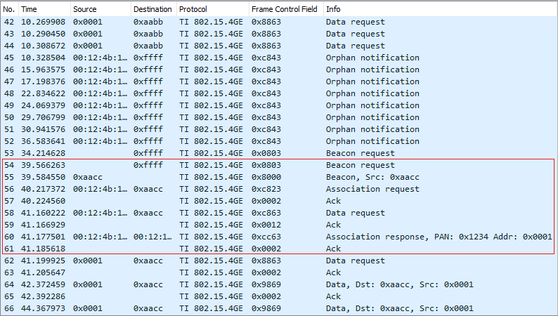 Figure 6-7 Packet Exchange Showing the Sensor Going Into an Orphan State and Switching PAN Coordinators
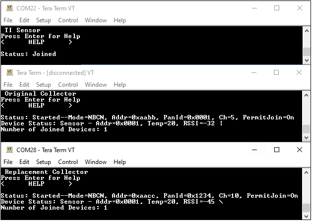 Figure 6-8 Common User Interface for the Sensor and Two Collectors After the First Collector is Disconnected