TIDUEY6 April 2021
- Description
- Resources
- Features
- Applications
- 5
- 1System Description
- 2System Overview
-
3Hardware, Software, Testing Requirements, and Test Results
- 3.1
Hardware Requirements
- 3.1.1
Hardware Overview
- 3.1.1.1
Control Module
- 3.1.1.1.1
Control Mother Board
- 3.1.1.1.1.1 Inverter Safing - UCC5870 ASC and Fault Control
- 3.1.1.1.1.2 DC-DC Safing
- 3.1.1.1.1.3 DC-DC Converter Secondary PWM Selection
- 3.1.1.1.1.4 Blower Fan Control
- 3.1.1.1.1.5 Voltage Monitor
- 3.1.1.1.1.6 Resolver Interface Control
- 3.1.1.1.1.7 Test Points on Control Module
- 3.1.1.1.1.8 General Purpose Ports
- 3.1.1.1.1.9 Connectors and Headers on Control Mother Board
- 3.1.1.1.2 Power Supplies
- 3.1.1.1.3 TCAN4550 module
- 3.1.1.1.4 Dual TCAN Module
- 3.1.1.1.5 Analog Back End Module
- 3.1.1.1.6 Resolver Analog Front End Module
- 3.1.1.1.1
Control Mother Board
- 3.1.1.2 Inverter Module
- 3.1.1.3 DC-DC Bidirectional Converter Module
- 3.1.1.1
Control Module
- 3.1.1
Hardware Overview
- 3.2 Resource Mapping
- 3.3 Test Setup
- 3.4 Test Results
- 3.1
Hardware Requirements
- 4General Texas Instruments High Voltage Evaluation (TI HV EVM) User Safety Guidelines
- 5Design and Documentation Support
- 6About the Author
1 System Description
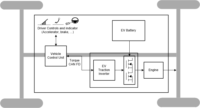
The power-train system is the core component in an electric vehicle as shown in Figure 1-1. It mainly contains three sub-modules, on board charger (OBC), traction inverter, and high voltage (HV) to low voltage (LV) DC-DC converter. The current trend in the industry is to integrate the OBC, traction inverter and DC-DC sub-systems into fewer enclosures, and control them with fewer MCU to reduce system cost and complexity. This will require MCU to have high real-time control performance. In this reference design, the traction inverter and bi-directional DC-DC converter are controlled with one C2000™ TMS320F28388D microcontroller. When this DC-DC is made bi-directional, it can be used to pre-charge the DC bus capacitor in the traction inverter system, which can reduce system cost by eliminating the current limiting relay and resistor.
 Figure 1-1 Electric Vehicle Power-Train
System
Figure 1-1 Electric Vehicle Power-Train
SystemFigure 1-2 shows the high-level block diagram of the Traction Inverter system. This reference includes a CAN FD interface to receive torque command, SiC inverter power stage with isolated sensing, and a resolver to digital converter system for position feedback.
 Figure 1-2 Electric Vehicle Traction
System
Figure 1-2 Electric Vehicle Traction
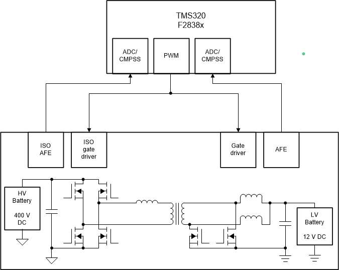
SystemThe block diagram of bi-directional DC-DC converter is shown in Figure 1-3. A phase shifted full bridge (PSFB) converter with synchronous rectification is. In this reference design, ZVS for switches in the one leg of the full bridge, and zero or low-voltage switching for switches in the other leg, is achieved. In this design, current doubler synchronous rectification is implemented on the secondary side with different switching schemes to achieve optimum performance under varying load conditions.
 Figure 1-3 DC-DC System Block
Diagram
 |
WARNING:
TI intends this reference design to be operated in a lab environment only and does not consider it to be a finished product for general consumer use. TI Intends this reference design to be used only by qualified engineers and technicians familiar with risks associated with handling high-voltage electrical and mechanical components, systems, and subsystems. There are accessible high voltages present on the board. The board operates at voltages and currents that may cause shock, fire, or injury if not properly handled or applied. Use the equipment with necessary caution and appropriate safeguards to avoid injuring yourself or damaging property. |


 |
CAUTION:
Do not leave the design powered when unattended. High voltage! There are accessible high voltages present on the board. Electric shock is possible. The board operates at voltages and currents that may cause shock, fire, or injury if not properly handled. Use the equipment with necessary caution and appropriate safeguards to avoid injuring yourself or damaging property. For safety, use of isolated test equipment with over-voltage and over-current protection is highly recommended. TI considers it the user's responsibility to confirm that the voltages and isolation requirements are identified and understood before energizing the board or simulation. When energized, do not touch the design or components connected to the design. Hot surface! Contact may cause burns. Do not touch! Some components may reach high temperatures >55°C when the board is powered on. The user must not touch the board at any point during operation or immediately after operating, as high temperatures may be present. |