TIDUEY6 April 2021
- Description
- Resources
- Features
- Applications
- 5
- 1System Description
- 2System Overview
-
3Hardware, Software, Testing Requirements, and Test Results
- 3.1
Hardware Requirements
- 3.1.1
Hardware Overview
- 3.1.1.1
Control Module
- 3.1.1.1.1
Control Mother Board
- 3.1.1.1.1.1 Inverter Safing - UCC5870 ASC and Fault Control
- 3.1.1.1.1.2 DC-DC Safing
- 3.1.1.1.1.3 DC-DC Converter Secondary PWM Selection
- 3.1.1.1.1.4 Blower Fan Control
- 3.1.1.1.1.5 Voltage Monitor
- 3.1.1.1.1.6 Resolver Interface Control
- 3.1.1.1.1.7 Test Points on Control Module
- 3.1.1.1.1.8 General Purpose Ports
- 3.1.1.1.1.9 Connectors and Headers on Control Mother Board
- 3.1.1.1.2 Power Supplies
- 3.1.1.1.3 TCAN4550 module
- 3.1.1.1.4 Dual TCAN Module
- 3.1.1.1.5 Analog Back End Module
- 3.1.1.1.6 Resolver Analog Front End Module
- 3.1.1.1.1
Control Mother Board
- 3.1.1.2 Inverter Module
- 3.1.1.3 DC-DC Bidirectional Converter Module
- 3.1.1.1
Control Module
- 3.1.1
Hardware Overview
- 3.2 Resource Mapping
- 3.3 Test Setup
- 3.4 Test Results
- 3.1
Hardware Requirements
- 4General Texas Instruments High Voltage Evaluation (TI HV EVM) User Safety Guidelines
- 5Design and Documentation Support
- 6About the Author
3.1.1.1.1.4 Blower Fan Control
The traction inverter deals with pretty high
power levels (about 10KVA) and that at high switching frequencies (40KHz), the switching
losses and conduction losses are pretty high (>300W). Since the EVM is a laboratory model
and is not supposed to be retrofitted into an EV/HEV, an appropriate blower cooled heatsink is
used to control the temperature of inverter power module. The blowers used are 12 V operated
(Dayton 2RTH4) and its speed can be regulated by C2000 MCU. The PWM
pulses from the C2000 MCU are driven by TI driver DRV8876-Q1 to boost the
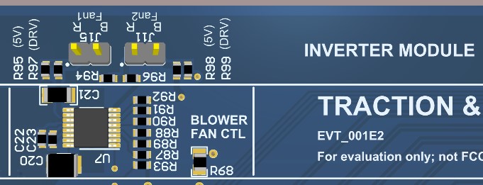
power levels before being applied to the fan motor. The section of the control mother board
hosting blower control is shown in Figure 3-7.
 Figure 3-7 Blower Fan controlResistors R97 and R99 should be populated with 0E to connect the driver with blower fans
. Headers J11 and J15 are where two blower motors can be connected. The blower fans can be
noisy running at 12 V and high speed. If such high speeds are not needed for any lab
evaluations (such as lower traction power levels), it can be reduced by adjusting the PWM
pulses from C2000.
 Figure 3-7 Blower Fan control
Note:
When low speed running of blower fans is preferred, they can be run off 5 V (intermediate power supply). The blowers can still blow some air good enough to move some heat away from heatsink. For this, 0E resistors is populated on R95 and R98, while removing the resistors R97 and R99. The user needs to monitor and ascertain the thermal safeness of such usage. If it is not enough, then discard this method.
CAUTION: With PWM control,
at lower duty cycles, the on chip free wheeling diode in DRV8876 will have a larger
conduction time. Since the diode drop is higher than the channel drop (during ON time), this
can lead to over heating of the driver if two fans are used together. To avoid this, either
the note given above could be used OR duty cycles above 65% could be used OR only one fan
can be used. In all these cases, ensure that the inverter heatsink is cooled down to safe
limits by the fan.