TIDUF00 November 2021
- Description
- Resources
- Features
- Applications
- 5
- 1System Description
- 2System Overview
-
3Hardware, Software, Testing
Requirements, and Test Results
- 3.1 Required Hardware and Software
- 3.2
Testing and Results
- 3.2.1 Test Setup
- 3.2.2
Test Results
- 3.2.2.1 Use Case – Vehicle, Bicycle, Pedestrian Detection
- 3.2.2.2 Use Case – Traffic Cone, Grocery Cart, Sign Pole, Pipe, Shrub
- 3.2.2.3 Use Case – Pedestrian Standing in Empty Parking Space
- 3.2.2.4 Use Case – Pedestrian Standing Next to Car
- 3.2.2.5 Use Case – Empty Parking Space
- 3.2.2.6 Use Case – Cross Traffic Alert
- 3.2.2.7 Use Case – Parking Block, Curb Detection
- 4Design Files
- 5Software Files
- 6Related Documentation
2.1.1 Automated Parking Software Block Diagram
The Automated Parking reference design software is based on the mmWave SDK demonstration software. Advanced Frame configuration is used to configure two sub-frames. One sub-frame is configured for 3D detection with maximum range of 10m and the second sub-frame is configured for 2D detection with maximum range of 50m.
Each sub-frame has independent chirping acquisition and processing times as shown in Figure 2-1.
 Figure 2-1 Multi-Mode Sub-Frames
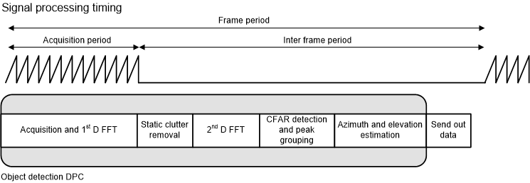
For each sub-frame the data path processing and timing has the same structure as shown in Figure 2-2.
 Figure 2-2 Datapath Processing and
Timing
Figure 2-2 Datapath Processing and
TimingThe processing chain consists of the following blocks, implemented on the HWA and the C674x DSP core of the AWR1843AOP.
- Range processing
- For each antenna, 1D windowing, and 1D fast Fourier transform (FFT)
- Range processing is interleaved with the active chirp time of the frame
- Doppler processing
- For each antenna, 2D windowing, and 2D FFT
- Then non-coherent combining of received power across antennas in floating-point precision
- Range-Doppler detection algorithm
- Constant false-alarm rate, cell averaging smallest of (CASO-CFAR) detection in range domain, plus CFAR-cell averaging (CACFAR) in Doppler domain detection, run on the range-Doppler power mapping to find detection points in range and Doppler space
- Angle estimation
- For each detected point in range and Doppler space, reconstruct the 2D FFT output with Doppler compensation, then a beamforming algorithm is applied to calculate the angle spectrum on the azimuth direction with multiple peaks detected. After that the elevation angle is estimated for each detected peak angle in azimuth domain.