JAJSCH6C June   2016  – June 2021 TPS62135

PRODUCTION DATA  

  1. 特長
  2. アプリケーション
  3. 概要
  4. Revision History
  5. Device Comparison Table
  6. Pin Configuration and Functions
  7. Specifications
    1. 7.1 Absolute Maximum Ratings
    2. 7.2 ESD Ratings
    3. 7.3 Recommended Operating Conditions
    4. 7.4 Thermal Information
    5. 7.5 Electrical Characteristics
    6. 7.6 Typical Characteristics
  8. Parameter Measurement Information
    1. 8.1 Schematic
  9. Detailed Description
    1. 9.1 Overview
    2. 9.2 Functional Block Diagram
    3. 9.3 Feature Description
      1. 9.3.1 Precise Enable
      2. 9.3.2 Power Good (PG)
      3. 9.3.3 Pin-Selectable Output Voltage (VSEL and FB2)
      4. 9.3.4 MODE
      5. 9.3.5 Undervoltage Lockout (UVLO)
      6. 9.3.6 Thermal Shutdown
    4. 9.4 Device Functional Modes
      1. 9.4.1 Pulse Width Modulation (PWM) Operation
      2. 9.4.2 Power Save Mode Operation (PWM/PFM)
      3. 9.4.3 100% Duty-Cycle Operation
      4. 9.4.4 HICCUP Current Limit And Short Circuit Protection (TPS62135 only)
      5. 9.4.5 Current Limit And Short Circuit Protection (TPS621351 only)
      6. 9.4.6 Soft-Start / Tracking (SS/TR)
      7. 9.4.7 Output Discharge Function (TPS62135 only)
      8. 9.4.8 Starting into a Pre-Biased Load (TPS621351 only)
  10. 10Application and Implementation
    1. 10.1 Application Information
      1. 10.1.1 Programming the Output Voltage
      2. 10.1.2 External Component Selection
      3. 10.1.3 Inductor Selection
      4. 10.1.4 Capacitor Selection
        1. 10.1.4.1 Output Capacitor
        2. 10.1.4.2 Input Capacitor
        3. 10.1.4.3 Soft-Start Capacitor
      5. 10.1.5 Tracking Function
      6. 10.1.6 Output Filter and Loop Stability
    2. 10.2 Typical Applications
      1. 10.2.1 Typical Application with Adjustable Output Voltage
        1. 10.2.1.1 Design Requirements
        2. 10.2.1.2 Detailed Design Procedure
        3. 10.2.1.3 Application Curves
      2. 10.2.2 Typical Application using VSEL and FB2
        1. 10.2.2.1 Design Requirements
        2. 10.2.2.2 Detailed Design Procedure
        3. 10.2.2.3 Application Curves
    3. 10.3 System Examples
      1. 10.3.1 LED Power Supply
      2. 10.3.2 Powering Multiple Loads
      3. 10.3.3 Voltage Tracking
      4. 10.3.4 Precise Soft-Start Timing
  11. 11Power Supply Recommendations
  12. 12Layout
    1. 12.1 Layout Guidelines
    2. 12.2 Layout Example
    3. 12.3 Thermal Considerations
  13. 13Device and Documentation Support
    1. 13.1 Device Support
      1. 13.1.1 Third-Party Products Disclaimer
    2. 13.2 Receiving Notification of Documentation Updates
    3. 13.3 サポート・リソース
    4. 13.4 Trademarks
    5. 13.5 静電気放電に関する注意事項
    6. 13.6 用語集
  14. 14Mechanical, Packaging, and Orderable Information

パッケージ・オプション

メカニカル・データ(パッケージ|ピン)
サーマルパッド・メカニカル・データ
発注情報

概要

TPS62135 および TPS621351 は、DCS-Control™ トポロジをベースにした、高効率で使いやすい同期整流降圧 DC/DC コンバータです。このデバイスは、3V~17V の広い範囲の入力電圧で動作するため、マルチセルのリチウムイオンおよび 12V の中間電源レールに適しています。このデバイスは、4A の出力電流を連続的に供給できます。TPS62135 は、負荷が軽いときに自動的にパワーセーブ・モードへ移行するため、負荷範囲全体にわたって高い効率が維持されます。このため、このデバイスは接続状態でのスタンバイ性能を必要とするアプリケーション、たとえば超低消費電力のコンピュータなどに最適です。MODE ピンが LOW になっているとき、デバイスのスイッチング周波数は、入力と出力の電圧に応じて自動的に調整されます。この手法は自動効率拡張機能 (AEE™) と呼ばれるもので、動作範囲の全体にわたって高い変換効率を維持します。PWM モードで 1% の出力電圧精度を実現しているため、出力電圧精度の高い電源を設計できます。

デバイスの静止電流は、標準で 18µA です。シャットダウン・モードでの電流は標準で 1µA で、TPS62135 では、出力がアクティブに放電されます。TPS621351 では、出力電圧放電機能がディセーブルされています。

TPS62135 は、調整可能バージョンとして、3mm × 2mm の VQFN パッケージで提供されています。

製品情報
部品番号パッケージ(1)本体サイズ (公称)
TPS62135VQFN3.00mm x 2.00mm
TPS621351
利用可能なすべてのパッケージについては、このデータシートの末尾にある注文情報を参照してください。
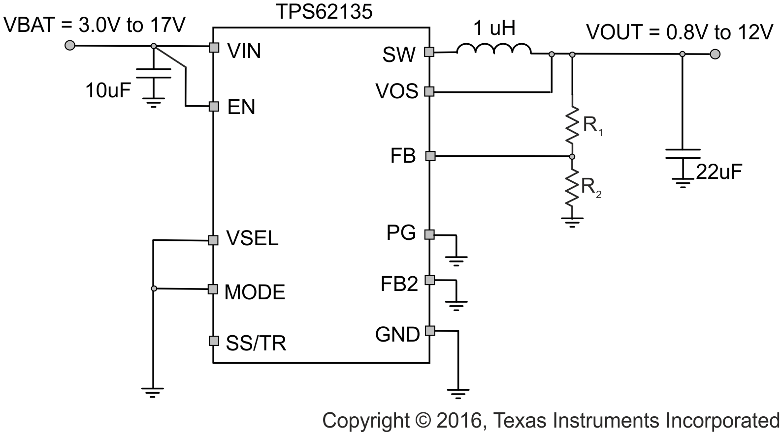
GUID-9EA48E8D-212A-4DEC-AF29-8143915F4AC4-low.gif概略回路図
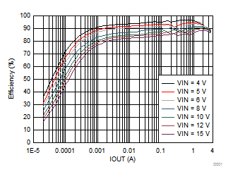
GUID-29D421A4-CA59-40E8-A1DB-A41356C99338-low.gif効率と出力電流との関係 Vo = 3.3V