SLLA305A May 2010 – September 2023 ESD441 , TPD12S015 , TPD12S015A , TPD12S016 , TPD12S520 , TPD12S521 , TPD13S523 , TPD1E05U06 , TPD1E10B06 , TPD1E10B09 , TPD1E6B06 , TPD1S414 , TPD1S514 , TPD2E001 , TPD2E001-Q1 , TPD2E009 , TPD2E1B06 , TPD2E2U06 , TPD2E2U06-Q1 , TPD2EUSB30 , TPD2EUSB30A , TPD2S017 , TPD3F303 , TPD3S014 , TPD3S044 , TPD4E001 , TPD4E001-Q1 , TPD4E004 , TPD4E02B04 , TPD4E05U06 , TPD4E05U06-Q1 , TPD4E101 , TPD4E1B06 , TPD4E1U06 , TPD4E6B06 , TPD4EUSB30 , TPD4F202 , TPD4S010 , TPD4S012 , TPD4S014 , TPD4S1394 , TPD4S214 , TPD5E003 , TPD5S115 , TPD5S116 , TPD6E001 , TPD6E004 , TPD6E05U06 , TPD6F002 , TPD6F002-Q1 , TPD6F003 , TPD6F202 , TPD7S019 , TPD8E003 , TPD8F003 , TPD8S009
- 1
- Abstract
- Trademarks
- 1Introduction
- 2Device Summary
- 3Pin Configuration and Functions
- 4Specifications
- 5Summary
- 6References
- 7Revision History
4.9.3 Capacitance vs. Bias Voltage
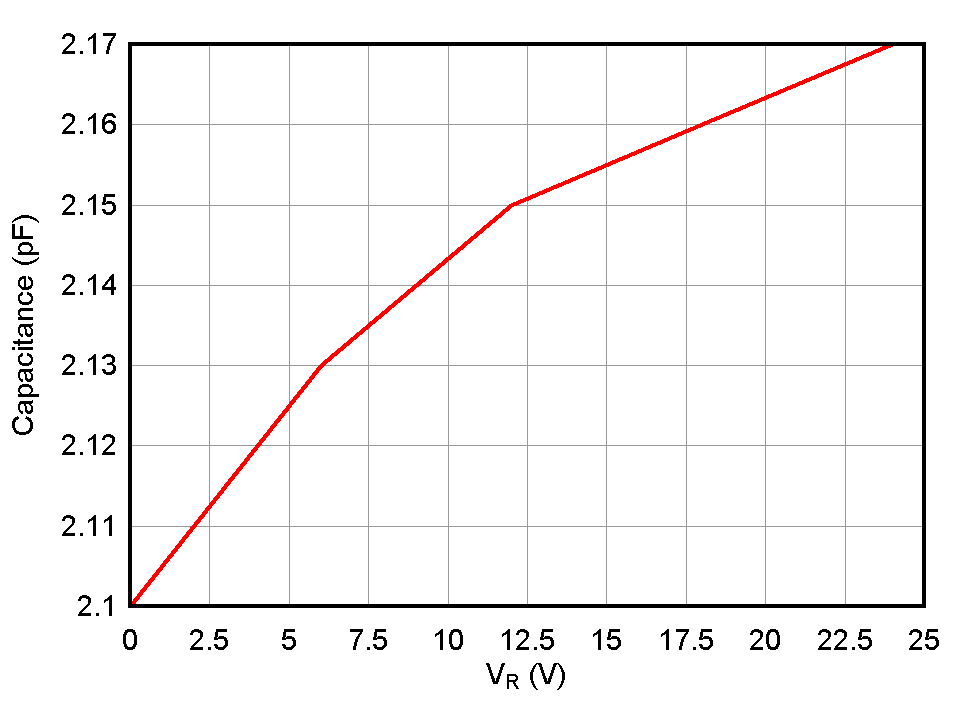
The capacitance vs bias voltage plot shows the variation in capacitance over the operating voltage. The plot shown below from the ESD751 data sheet depicts a bi-directional device only showing the positive operating range, 0 to 24-V. As seen in the plot, the capacitance varies slightly across the positive operating voltage.
 Figure 4-6 Capacitance vs Bias
Voltage