SLOA277B january 2019 – july 2023 LM124 , LM124-N , LM124A , LM158 , LM158-N , LM158A , LM224 , LM224-N , LM224A , LM258 , LM258-N , LM258A , LM2902 , LM2902-N , LM2902-Q1 , LM2902K , LM2902KAV , LM2904 , LM2904-N , LM2904-Q1 , LM2904B , LM2904B-Q1 , LM2904BA , LM321 , LM324 , LM324-N , LM324A , LM358 , LM358-N , LM358A , LM358B , LM358BA , TS321 , TS321-Q1
5.3 Low VCC Audio Amplifier Example
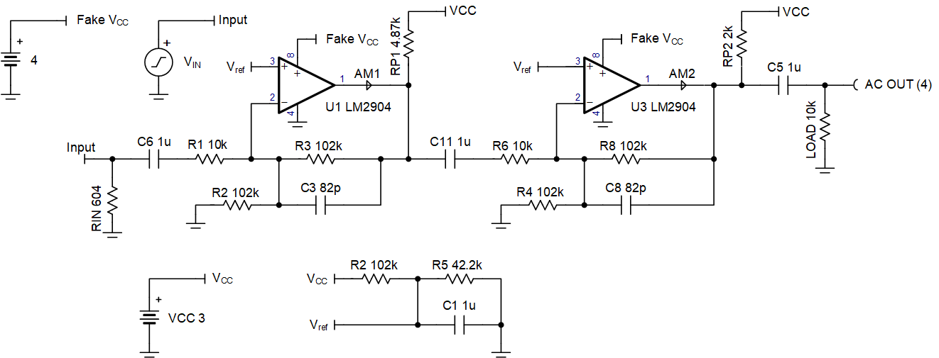
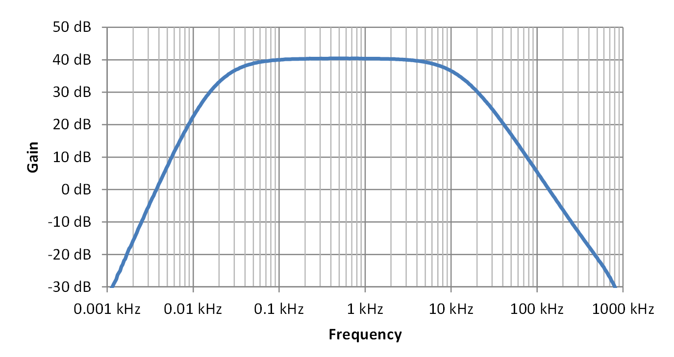
To demonstrate that 3 V is a usable yet challenging supply voltage, an example involving a 3-V audio pre-amplifier with LM2904DR is considered (see Figure 5-2). This amplifier has a 40-dB bandpass gain and –3-dB corners at 30 Hz and 10 kHz. Pull up resistors (RP1, RP2) were added to increase the output range to 0.9 V to 2.7 V at the worst case temperature of –40°C. For a maximum output swing without clipping, an output bias point of 1.76 V was used, which is halfway between the expected VOL and VOH values, and the input bias point is was at half of the output, 0.88 V because it is simple and meets the 0-V to 1-V input range. Higher temperature will improve the VOL range and a higher VCC will improve the VOH range. This means there is more design margin against low peak output clipping at warmer temperatures and more design margin against high peak output clipping with a larger VCC.
 Figure 5-2 3-V Audio Bandpass Amplifier
Schematic
Figure 5-2 3-V Audio Bandpass Amplifier
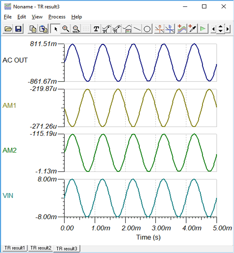
SchematicFor the resulting simulation to work correctly, a "fake" VCC set to 4 V was used because the LM2904 model does not support pull up resistors that improve VOH. The model fights the pull up resistor, but real-world devices will not do so. AM1 and AM2 simulation meters are used to check the output current's magnitude and polarity. Ensure the current meters are more negative than –100 µA. The current needs to be greater than a strong constant current sink sample so the PNP emitter follower always conducts some current to prevent crossover time delay. Figure 5-3 is the simulation result for the output voltage and output currents. The minimum negative output current is more negative than –100 µA with an 8-mV peak input signal.
 Figure 5-3 Simulation of 1-kHz Sine Wave Transient
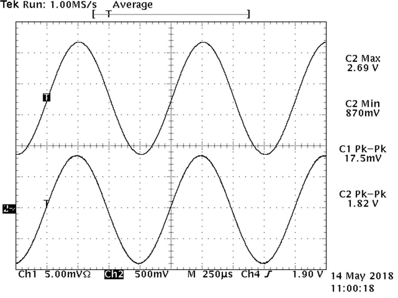
Figure 5-4 shows the bench test results for VCC = 3 V at Ta = –40°C. From the resulting plots, the maximum output without clipping was 1.82 Vpp. The top waveform is the U3 output and the bottom waveform is the input signal. Figure 5-5 shows the plot of gain vs frequency at VCC = 3 V, Ta = 25°C.
From this discussion we can conclude that 3-V supply designs can be used successfully. However, applications using 5-V or higher supply will be easier to design.
 Figure 5-4 Bench Testing 1-kHz Maximum Amplitude Without Clipping Waveforms
 Figure 5-5 Amplifier Voltage Gain vs Frequency