SPRAD24 august 2023 AM2631 , AM2632 , AM2632-Q1 , AM2634 , AM2634-Q1 , AM263P2-Q1 , AM263P4 , AM263P4-Q1
- 1
- Abstract
- Trademarks
- 1Introduction
- 2AM263x Overview
- 3Guide to Running TIDM-02014 Traction Inverter
- 4Brief Guide to Code Migration
- 5Summary
- 6References
3.1 Software Set-up
After setting up the traction system as shown in the Figure 2-3, the TIDM-02014 reference design needs the software environment to be set-up to run it. We used Code Composer Studio (CCS) as the integrated development environment for this purpose.
As a first step, please download and install CCS version 12.2.0 or newer that is recommended for this project. CCS User's Guide provides more details about CCS installation and use.
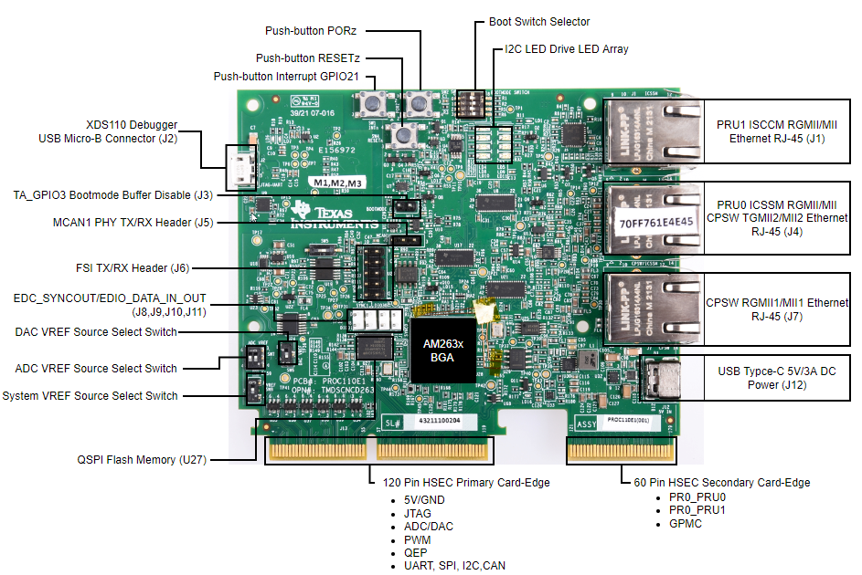
While it is not strictly necessary, establishing a real time debug interface helps a lot in debugging any power conversion application with an MCU. For AM263x, real time debug is enabled by UART connection between CCS and AM263x. The user interfaces of the AM263x control card are shown in Figure 3-1. The details on hardware connection can be found in AM263x Control Card User's Guide. The control card offers both JTAG and UART debugging ports in one USB Micro-B connector. A detailed explanation of creating a target configuration file for the debug ports can be found in the application note AM263x for Traction Inverters. As this application note also covers in detail how to configure control peripherals, interrupts and driver interfaces, we are not repeating those sections here.
 Figure 3-1 User Interfaces of AM263x Control Card