SBAA510 October 2021 DRV5032 , TMAG5170 , TMAG5231 , TMAG5273
5.1 DRV5032 Test Setup
The first test compares the performance of the Reed switch and the DRV5032 hall effect switch. For this test, several distances from each side of the X-axis are chosen for detection sensitivity. The Z-axis value is also varied to show sensitivity over multiple measurement nodes in the {Z,Y} plane. This test set also includes an identical testing process with variation nodes on the {X, Z} plane to show sensitivity dependency with respect to device positioning. Figure 5-1 shows the magnet approaches used for both tests.
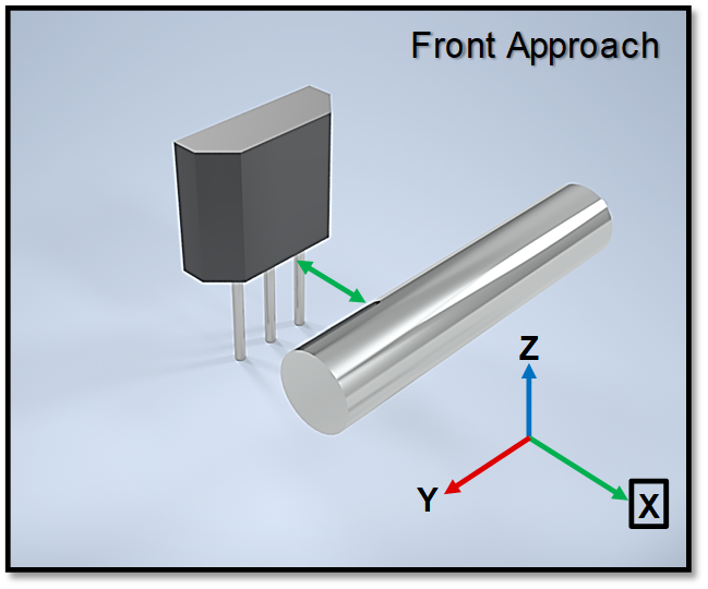 | 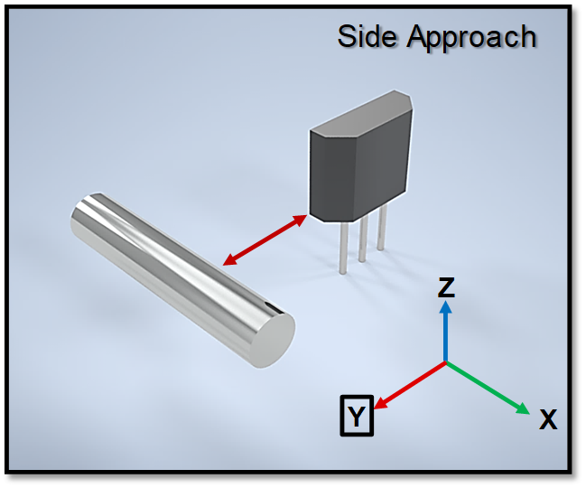 |
The cylindrical magnet used in this test is magnetized through the length of the body. This creates a very low flux value at the center point of the magnet. For this reason, the center-point position along the y-axis provides no useful testing results for the DRV5032, but is added for accurate modeling purposes.
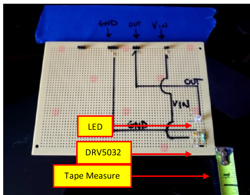
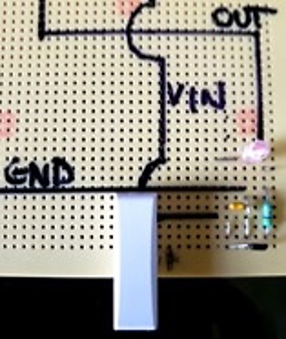
For each respective nodal coordinate (Y-axis, Z-axis), the magnet is slowly moved towards the device and the distance recorded. A standard tape measure is used for measuring the detection distance at an accuracy of 1/16th (0.0625) in. In the case of the DRV5032, the device is powered from a stable 3.3V DC power supply and populated on a small breadboard. An LED is also leveraged for visual indication of detection as well. The tape measure is only used to measure distance to the DRV5032 after the fact from a mark on a piece of masking tape and is removed during testing to negate any influence from the metal. This is shown in Figure 5-2.
 |  |