SBAA510 October 2021 DRV5032 , TMAG5170 , TMAG5231 , TMAG5273
7.1 TMAG5170 Test Setup
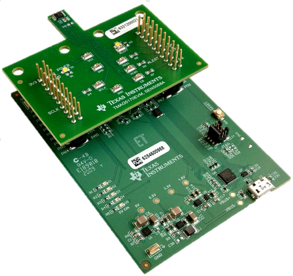
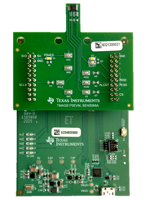
For the TMAG5170 test setup, we leverage the TMAG5170EVM shown in Figure 7-1. This board provides all necessary connections from the TMAG device for communication with the evaluation GUI. The device is located on a protruding cantilever to isolate from the rest of the board. The measurement process in this case is the same as for the DRV5032 and Reed switch with static nodal points in the first two axes and the variance being introduced on the third.
 |  |
In addition to device placement, there are several parameters which can be adjusted within the GUI for different detection scenarios. For the purpose of this test, the following configuration parameters were used:
TMAG settings
- Configuration mode
- Conversions: as fast as possible
- All axes active
- 50mT range
- Magnitude calculated from X and Y axes.
Magnet: K&J Magnetics D4X0
- N42 cylindrical magnet
- Constant orientation
- Moved across grid in ¼ inch steps
The TMAG5170 testing is accomplished slightly different than the sliding door tampering method due to the nature of the device and the linear output capabilities for all three axes. In addition to bringing the magnet closer to the device on a particular axis, the device is also positioned at a 45-degree angle as well to gain an understanding of the device’s response when the field is oriented on a plane rather than just an axis.
 Figure 7-2 TMAG5170 Magnetic Approach Directions
This test only includes one approach data set as the other two axes would be comparatively the same as far as device response and output from the GUI. For this test, the axis of approach is the X axis shown in Figure 7-3 and Figure 7-4). The secondary test is on the X, Y plane at a 45-degree angle approach shown in Figure 7-4.
 Figure 7-3 TMAG5170 X-Axis Approach
 Figure 7-4 TMAG5170 45-Degree Angle Approach