SBAA510 October 2021 DRV5032 , TMAG5170 , TMAG5231 , TMAG5273
5.4 Front Approach Results
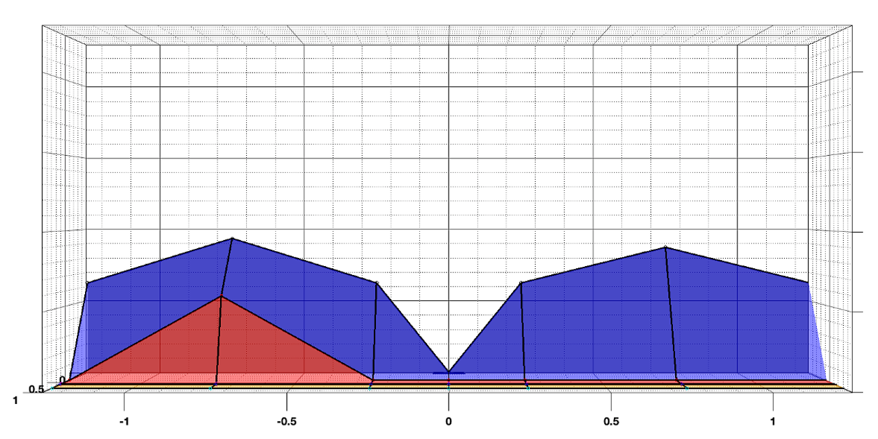
Figure 5-4 shows a top down three-dimensional mapping of the magnetic detection field of the DRV5032 with a top down view. From this visual, it can be seen that the maximum distance from the device that the magnet was detected was slightly less than 1 inch. As expected, there is a point in the center where the magnet was not detected, due to the magnetization characteristics of the magnet used in testing.
 Figure 5-4 DRV5032 Front Approach Magnetic Detection Field: Top Down View
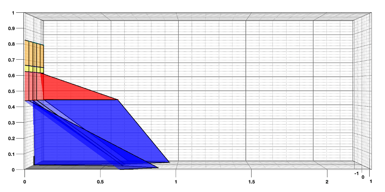
Figure 5-5 shows a side (X,Z plane) view of the detection field. This provides more details on the detection distance now adding in the sensitivity over variable height nodes. The detection height tapers sharply at approximately 0.45 inches above the DRV5032 and becomes imperceptible slightly higher than 0.6 inches on the right side (facing front of device). The variance between the left and right side can most likely be attributed to test setup limitations with respect to absolute accuracy.
 Figure 5-5 DRV5032 Front Approach Magnetic Detection Field: Side View
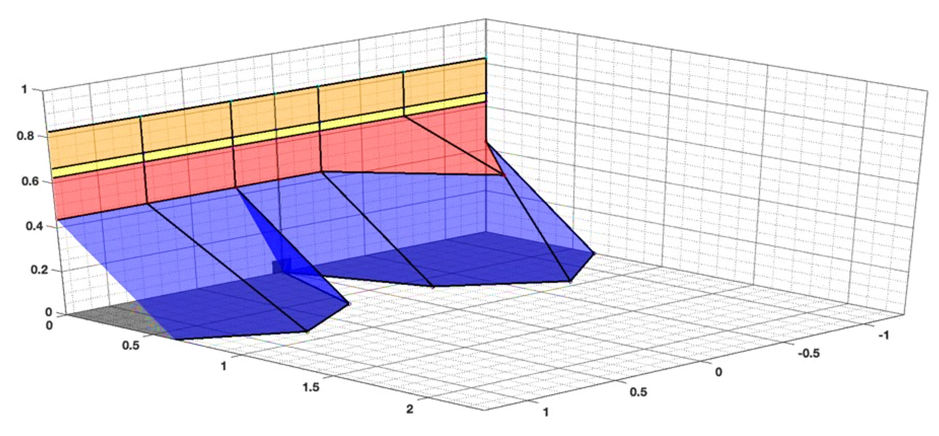
Finally, Figure 5-6 shows an off-axis view of the magnetic sensitivity for a big picture snapshot of the results. All of the previously mentioned key portions of the results are shown together in this plot.
 Figure 5-6 DRV5032 Front Approach Magnetic Detection Field: Off-Axis View