SBAA510 October 2021 DRV5032 , TMAG5170 , TMAG5231 , TMAG5273
5.5 Side Approach
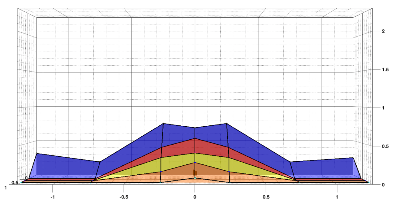
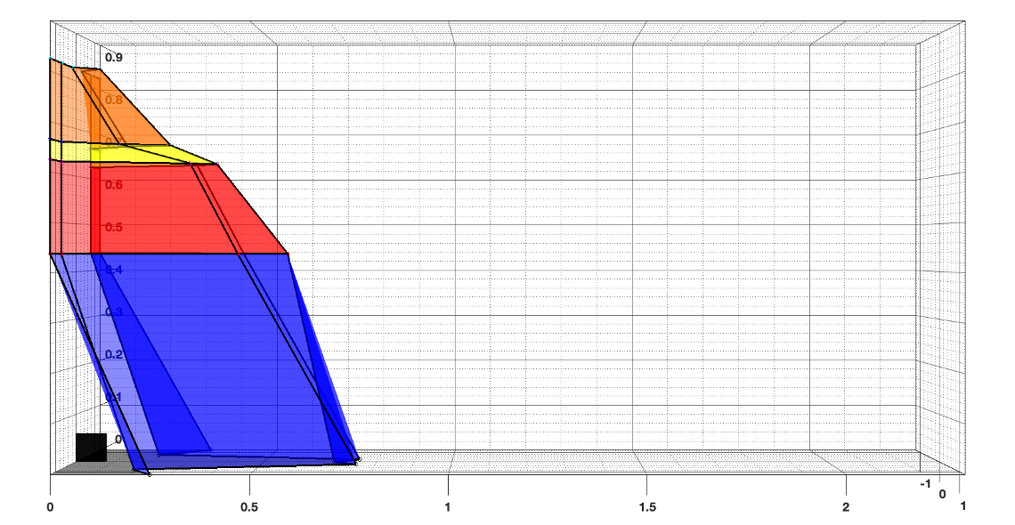
For the side approach, Figure 5-7 and Figure 5-8 show the resulting detection field using the approach shown in Figure 5-6. The detection field is very symmetrical along the X-axis with a maximum detection distance of approximately 0.75 inches at 0.25 inches in either direction off the axis, with the detection tapering from this point outwards.
 Figure 5-7 DRV5032 Side Approach Magnetic
Detection Field Results: Top Down View
 Figure 5-8 DRV5032 Side Approach Magnetic
Detection Field Results: Side View
Figure 5-8 DRV5032 Side Approach Magnetic
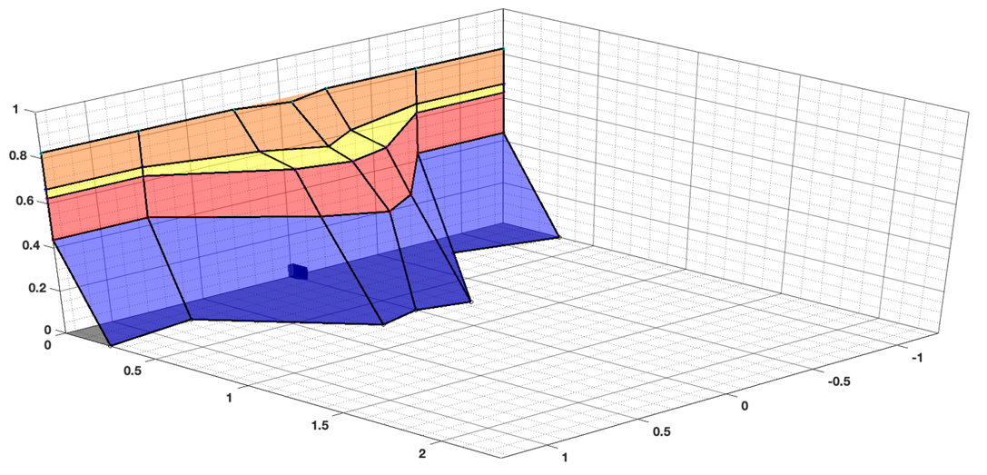
Detection Field Results: Side ViewFigure 5-9 shows the DRV5032 side approach field to better show the axes values and the field shape. The Z axis height sharply tapers at 0.6 inches above the device and is no longer perceptible after approximately 0.8 inches.
 Figure 5-9 DRV5032 Side Approach Magnetic
Detection Field Results: Off-Axis View