SBAA510 October 2021 DRV5032 , TMAG5170 , TMAG5231 , TMAG5273
3 Hall Effect Sensor Overview
Hall effect sensors, unlike Reed switches, are IC devices that can also be used to detect magnetic fields. Some of the Hall Effect sensors Texas Instruments offers, such as the TMAG5273 and the TMAG5170, can even provide 3D spacial magnetic sensing with a linear output. Others offer a binary output just as the Reed switch when a magnetic field is detected on a particular axis. If we were to use a DRV5032 with a 1.8 V supply voltage on VCC and 5 samples per second, the average current consumption would be only 540nA which provides a great low-power option for Reed switch replacement.
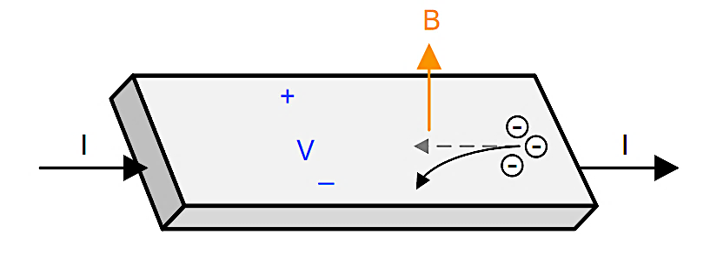
Hall Effect sensors detect the voltage difference (V) that develops on a conductor carrying an electrical current (I) in the presence of a magnetic field (B) as shown in Figure 3-1.
 |
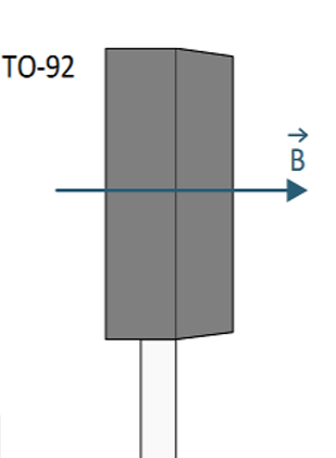 |
By integrating this electrophysical property into an IC, the magnetic field can be detected just as with the Reed switch. If we look at the DRV5032 schematic below, we see an example of this application leveraging a microcontroller to detect the binary output from the device. The distance of detection can be adjusted through the available magnetic threshold sensitivity variations of the product. For the testing included within this paper, we are using the omni-polar FB version of the device in a TO-92 package. More specific information on this device can be found on the DRV5032 product page on TI.com. Hall-effect switches such as the DRV5032 are suitable for applications where a simple open or close status is sufficient. This device is also very low power as well, in the nano-amp range for a 5-sample period per second. This is especially useful in battery powered applications where the design engineer must mitigate as much additional power consumption possible. An example application of the DRV5032 is shown in Figure 3-2.
 Figure 3-2 DRV5032 Application Example
Another great option for more detailed detection scenarios are linear 3D Hall-effect sensors such as the TMAG5170, which was used for testing throughout this document, and the TMAG5273. These devices are better suited for more advanced detection schemes where 3 axis detection is needed or preferred. Leveraging a 3-axis device allows for tamper detection on all three planes by using the normal use magnetic output as a reference point for activities. If the linear output from the device, assuming a normal idle state, is shown to vary at any point, an alert can be sent to the device owner letting them know that the sensor has detected an abnormal condition on that particular door and or window. Figure 3-3 shows an example application of the TMAG5170 with a companion host MCU.
 Figure 3-3 Application Block Diagram
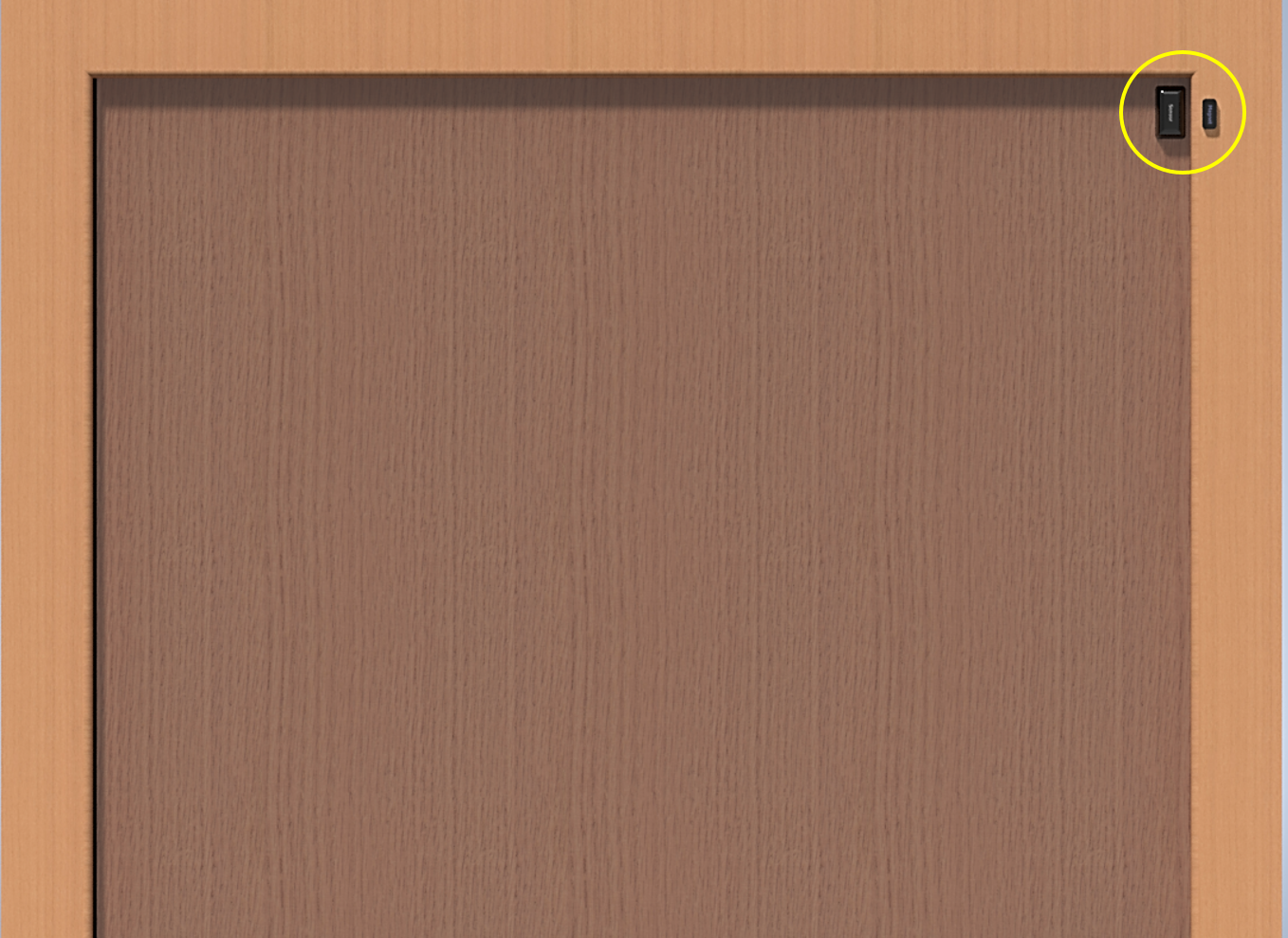
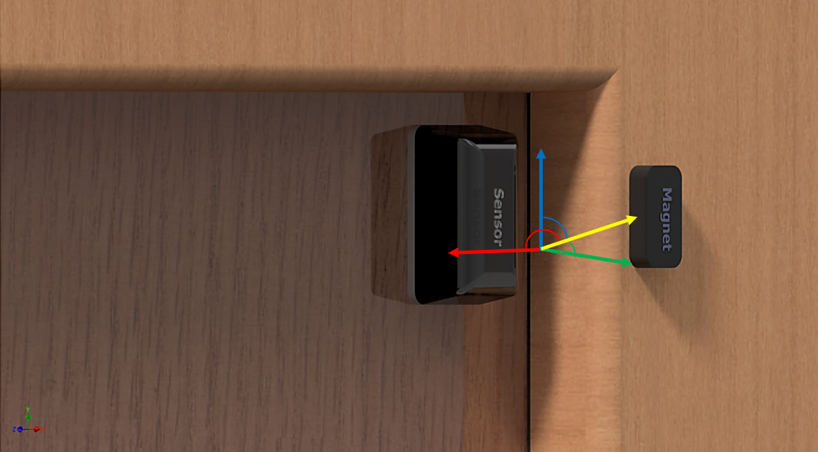
Linear 3D Hall-effect sensors are also a good option for sensors that require variations in mounting such as the mounting position shown in Figure 3-4. Here the door frame is raised from the door itself which creates a delta distance in both X and Y axes. While the Reed switch can still potentially work here, there are more stringent placement restrictions due to the distance and orientation of the magnet. The 3-axis TMAG devices have the ability to detect the special position of the magnet accounting for the offset added from the door frame.
 |  |