SBAA510 October   2021 DRV5032 , TMAG5170 , TMAG5231 , TMAG5273


  1.   Trademarks
  2. 1Introduction
  3. 2Reed Switch Overview
  4. 3Hall Effect Sensor Overview
  5. 4Performance Comparison
  6. 5DRV5032 Test Setup and Results
    1. 5.1 DRV5032 Test Setup
    2. 5.2 Understanding the Results
    3. 5.3 DRV5032 Test Results
    4. 5.4 Front Approach Results
    5. 5.5 Side Approach
    6. 5.6 Tamper Susceptibility Testing Setup
    7. 5.7 Tamper Susceptibility Test Results
  7. 6Reed Switch Test Setup and Results
    1. 6.1 Reed Switch Test Setup
    2. 6.2 Reed Switch Test Results
    3. 6.3 Front Approach Results
    4. 6.4 Side Approach Results
    5. 6.5 Tamper Susceptibility Testing Setup
    6. 6.6 Reed Switch Tamper Susceptibility Test Results
  8. 7TMAG5170 Test Setup and Results
    1. 7.1 TMAG5170 Test Setup
    2. 7.2 TMAG5170 Test Results
    3. 7.3 TMAG5170 Tamper Susceptibility Testing Setup
    4. 7.4 TMAG5170 Tamper Susceptibility Test Results
  9. 8Summary

Tamper Susceptibility Testing Setup

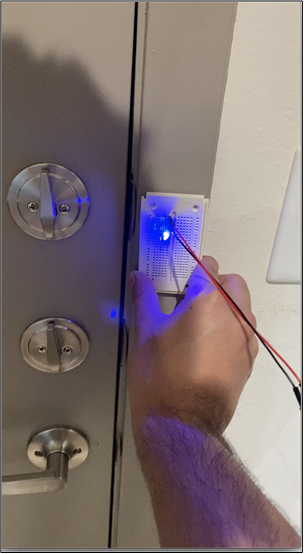
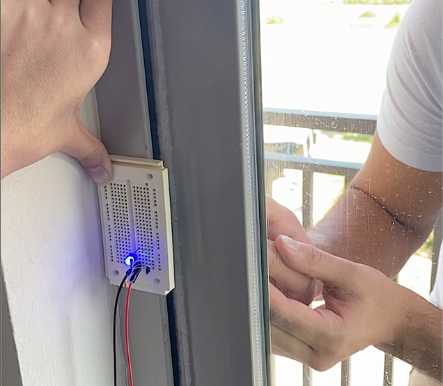
For this test, a sliding glass door and a typical entry door is used as the main mounting point for the Reed switch and the DRV5032 tamper test. The device mounting is altered in a way to make testing more practical while imitating a typical placement for the device in a home or business. For each test, the magnet is brought closer to the door for the opposite (outside) side until the LED goes off, indicating that the sensor has detected the tamper magnet’s field. Both door scenarios are shown in Figure 5-10.

GUID-20210810-SS0I-8NDP-PPDL-SHRZLVVZ8PDG-low.pngGUID-20210810-SS0I-T17X-SFP9-FT54WRXBG04M-low.png

Figure 5-10 DRV5032 Tamper Test Setup