SBAU378A September 2021 – January 2022 ADS1148 , ADS1248
- Trademarks
- 1Introduction
- 2Getting Started With the ADS1x48EVM
-
3ADS1x48EVM Overview
- 3.1 Analog and Digital Power Supplies
- 3.2 Voltage Reference Options
- 3.3 Clock Options
- 3.4 Digital Interface
- 3.5
Analog Input Connections
- 3.5.1 Connecting a Thermocouple to J5 on the ADS1x48EVM
- 3.5.2 Connecting a Thermistor to J5 on the ADS1x48EVM
- 3.5.3
Connecting an RTD to J6 on the ADS1x48EVM
- 3.5.3.1 Connecting a 2-Wire RTD Using a Low-Side RREF to J6 on the ADS1x48EVM
- 3.5.3.2 Connecting a 2-Wire RTD Using a High-Side RREF to J6 on the ADS1x48EVM
- 3.5.3.3 Connecting a 3-Wire RTD Using One IDAC and a Low-Side RREF to J6 on the ADS1x48EVM
- 3.5.3.4 Connecting a 3-Wire RTD Using One IDAC and a High-Side RREF to J6 on the ADS1x48EVM
- 3.5.3.5 Connecting a 3-Wire RTD Using Two IDACs and a Low-Side RREF to J6 on the ADS1x48EVM
- 3.5.3.6 Connecting a 3-Wire RTD Using Two IDACs and a High-Side RREF to J6 on the ADS1x48EVM
- 3.5.3.7 Connecting a 4-Wire RTD Using a Low-Side RREF to J6 on the ADS1x48EVM
- 3.5.3.8 Connecting a 4-Wire RTD Using a High-Side RREF to J6 on the ADS1x48EVM
- 3.5.3.9 Summary of ADS1x48EVM RTD Configuration Settings
- 3.5.4 Connecting a General-Purpose Input to J5 on the ADS1x48EVM
- 4ADS1x48EVM GUI
- 5Bill of Materials, Printed Circuit Board Layout, and Schematic
- 6Revision History
2 Getting Started With the ADS1x48EVM
The following list of steps provides an overview to quickly get the ADS1x48EVM setup and operational. The subsequent sections in this document expand on each step in order to explain in detail the available features on the ADS1x48EVM and the corresponding GUI. Links are provided to navigate from this quick-start guide to the appropriate section at each step, where applicable.
- Remove the ADS1x48EVM, PAMBoard, and USB cable from the ADS1x48EVM box.
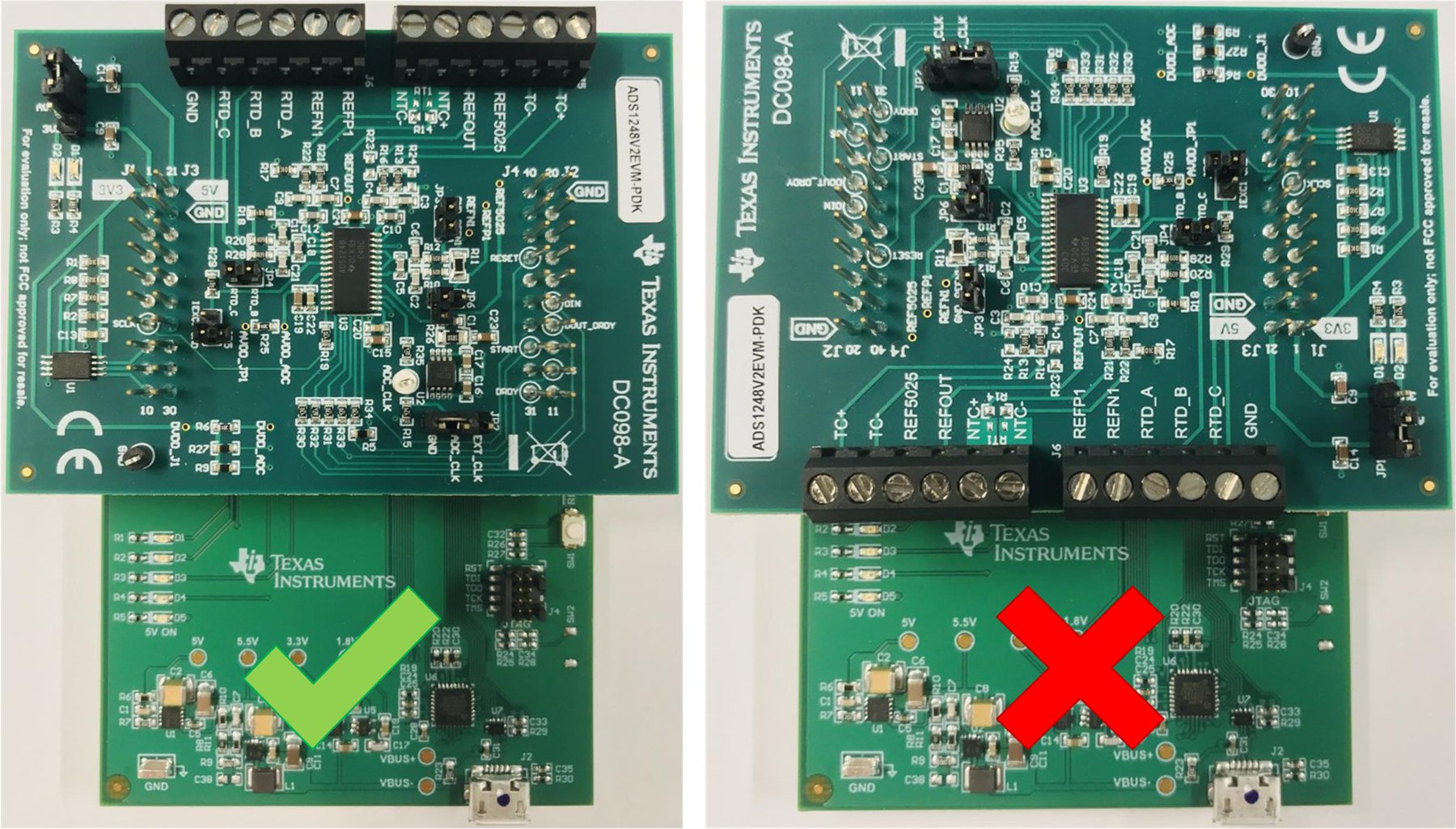
- If necessary, connect the ADS1x48EVM to the PAMBoard as shown in the left image in Figure 2-1.
- Set the ADS1x48EVM jumpers to the desired location:
- Power
- Clock
- RTD connections (if applicable)
- Connect the micro-USB-to-USB cable from the PAMBoard directly to a USB port on the computer. Do not connect the cable through a USB hub.
- Open up the web-based GUI available on the EVM
landing page (ADS1148EVM-PDK or ADS1248EVM-PDK).
- First-time users may be prompted to download and install the browser extension for Firefox™ or Chrome™ and the TI Cloud Agent Application. Installing the TI Cloud Agent is a one-time download and installation.
- Refresh the GUI such that a green signal displays and the Hardware Connected indicator shows in the bottom status ribbon (see Figure 4-2).
- Select the desired ADC reference voltage.
- Connect your sensors or signals to the input terminal blocks (J5 and J6).
- Capture and analyze data using the GUI.
 Figure 2-1 Connecting the ADS1x48EVM to the PAMB Board