SBAU382A November 2021 – January 2022 ADS7029-Q1 , ADS7039-Q1 , ADS7040 , ADS7041 , ADS7042 , ADS7043 , ADS7044 , ADS7046 , ADS7047 , ADS7049-Q1 , ADS7052 , ADS7054 , ADS7056 , ADS7057
4.1 Connecting the Hardware
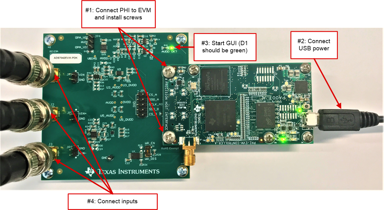
After installing the software, connect the EVM as shown in Figure 4-1:
- Physically connect P2 of the PHI to J4 of the ADS704X-5XEVM. Install the screws to ensure a robust connection
- Connect the USB cable from the PHI to the computer first:
- LED D5 on the PHI lights up, indicating that the PHI is powered
- LEDs D1 and D2 on the PHI start blinking to indicate that the PHI is booted up and communicating with the PC; Figure 4-1 shows the resulting LED indicators
- Start the software GUI. The LEDs blink slowly as the FPGA firmware is loaded on the PHI. This loading takes a few seconds and then the AVDD and DVDD power supplies turn on. LED D1 on the ADS704X-5XEVM (as shown in Figure 4-1) illuminates green to indicate that AVDD is being supplied to the EVM
- Connect the signal generator. The input range varies for the different ADCs,
but is typically 0 V to AVDD for single-ended devices or –AVDD to +AVDD for
differential devices. Check the specific ADC data sheet for more information about allowable input ranges. In
any case, adjust the input signal to just below full-scale range to avoid clipping
- Texas Instruments offers the PSIEVM as a precision signal generator if such a source is otherwise unavailable to the user. The PSIEVM can be used to generate clean sinusoidal input signals for the ADS704X-5XEVM to verify AC performance specifications.
 Figure 4-1 Hardware Connections on the
ADS704X-5XEVM