SLAAED0 March 2024 TAS2764 , TAS2780 , TAS2781
- 1
- Abstract
- Trademarks
- 1 Introduction
- 2 Measurement Methodology
- 3 Introduction to Noise-gate and Pop in Class-D Amplifiers
- 4 Causes of Pop in TAS27xx family of Class-D Amplifiers
- 5 Click and Pop Using TAS27xx
-
6 Click and Pop Measurement Technique Using
AP v6.0. 2
- 6.1 Measurement Setup
- 6.2 Filter Settings
- 6.3 Data Capture Settings
- 6.4 Auto Range Settings for Pop Measurement
- 6.5 ASI or I2S Configurations for Pop Measurement
- 6.6 APx Sound Level Meter Utility
- 6.7 Data Acquisition
- 6.8 Interpreting Click and Pop Waveforms
- 6.9 Post Processing of AP Waveforms
- 6.10 A-Weighted Click and Pop Numbers
- 6.11 Exporting the A-Weighted Numbers
- 7 Noise-Gate Pop and Measurement Technique Using APx
- 8 Configuring TAS2764 for Improved Click and Pop Noise Performance
- 9 Summary
- 10References
8.1 Explanation
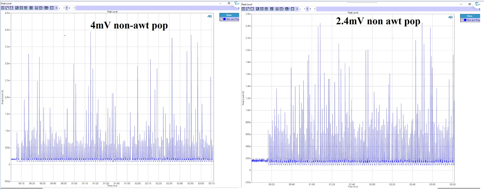
Pop minimization is done through forcing the device into idle channel mode before power down of the device and exiting from idle channel mode post power up. This is done to effectively stagger the shutdown pop in the device. This device optimization is already taken care In TAS2780 and TAS2781 in internal device power up or power down configurations. Figure 8-1 shows the click and pop measured on 1 device in Powermode1 Configuration of the device before and after applying the script.
 Figure 8-1 Hardware Configurations
Required for Measurement of Click and Pop