SLLA497 September 2020 TMS320F28P550SG , TMS320F28P550SJ , TMS320F28P559SG-Q1 , TMS320F28P559SJ-Q1
3.6 Three-phase TNPC Three-level PFC
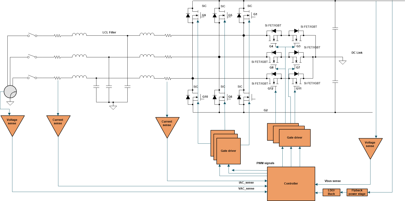
Figure 3-8 depicts the basic topology of the 3L T-Type converters. The conventional two-level Voltage Source Converter (VSC) topology is extended with an active, bidirectional switch to the DC-link midpoint. For 800-V DC link voltages, the high-side and the low-side on each phase would usually be implemented with 1200-V IGBTs/diodes as the full voltage has to be blocked. Differently, the bidirectional switch to the DC-link midpoint has to block only half of the voltage. It can be implemented with devices having a lower voltage rating like two 600-V IGBTs including antiparallel diodes. Due to the reduced blocking voltage, the middle switch shows very low switching losses and acceptable conduction loss. Contrary to the previously-discussed three-level NPC topology, there is no series connection of devices that has to block the whole DC-link voltage. For the NPC topology, switching transitions directly from the positive (P) to the negative (N) DC-link voltage level and vice versa are usually omitted as there might occur an uneven share of the voltage to be blocked in the transient case when both FETs connected in series turn off at the same time. This undesirable effect cannot occur in the T-type topology. It is not necessary to implement low-level routines which prevent such transitions or ensure a transient voltage balancing among series connected IGBTs. Another additional benefit related to using single 1200-V devices to block the full DC-link voltage is reduced conduction losses. Whenever the output is connected to (P) or (N), the forward voltage drop of only one device occurs, contrary to the NPC topology where always two devices are connected in series. The conduction losses are considerably reduced making the T-type an interesting choice even for low switching frequencies.
Overall, the conduction losses are significantly lower when compared with NPC but the switching losses are high due to the devices which block the full DC link voltage. Due to limited component count when compared to NPC topology and better efficiency, power density and bidirectional operation capability when compared to Vienna Rectifier and two level PFC, the T-type rectifier is best suited for applications upto 50-khz switching frequency beyond which NPC performs better. One of the drawbacks of this topology is the high peak voltage stress across the high voltage blocking FETs. Finally, similar to the other topologies this also has a good THD performance, so it does not require bulky inductor at the input. TI's Three-level, three-phase SiC AC-to-DC converter reference design contains details on the implementation of this converter.
 Figure 3-8 Three-phase Three-level T-type
PFC.