SLLA497 September 2020 TMS320F28P550SG , TMS320F28P550SJ , TMS320F28P559SG-Q1 , TMS320F28P559SJ-Q1
3.2 Single-phase Neutral Point Clamped PFC
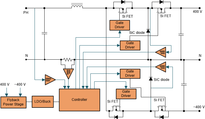
Figure 3-3 shows a typical neutral point clamped PFC topology in an EV charging station.
 Figure 3-3 Neutral Point Clamped PFC.
 This topology has several advantages over a conventional two-level converter. First multilevel converters not only can generate the output voltages with very low distortion, but also can reduce the dv/dt stresses with lower voltage across the power switches; therefore, electromagnetic compatibility (EMC) problems can be reduced. Secondly, multilevel converters can draw input current with low distortion and hence they have better total harmonic distortion performance and require less bulky input inductors. The multilevel feature of this topology enables more cost-effective MOSFETs to be utilized, further reducing the cost of the design. GaN/SiC can be used in this topology when very high efficiency and power density are needed. Finally active switches allow bidirectional operation of the converter. One particular disadvantage is the greater number of power semiconductor switches needed. Although lower voltage rated switches can be utilized in a multilevel converter, each switch requires an isolated gate drive circuit which can be quite costly and challenging to design.