SLLA497 September 2020 TMS320F28P550SG , TMS320F28P550SJ , TMS320F28P559SG-Q1 , TMS320F28P559SJ-Q1
3.1 Single-phase Totem Pole PFC
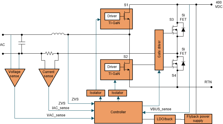
Figure 3-1 shows the totem pole PFC topology which is a conventional boost PFC where one half of the diode bridge is replaced by active switches S1 and S2 in a half bridge configuration, hence the name “totem pole”. The diode S3 and S4 forms the slow 50- to 60-Hz line frequency leg which can either be slow AC rectifier diodes or can be replaced by low-RDS(on) synchronous MOSFETs for improved efficiency.
 Figure 3-1 Totem Pole PFC.
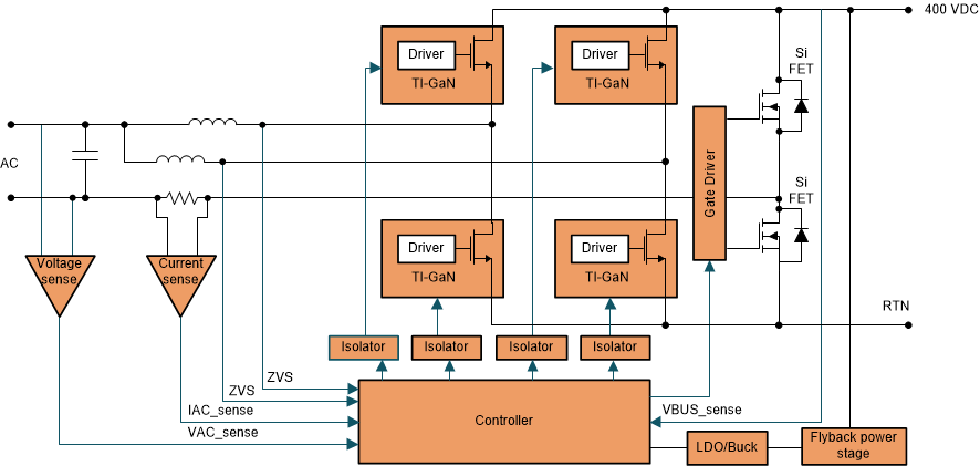
 The totem pole PFC has the advantages of improved efficiency. The main current only flows through two switches at a time. S1 and S2 are driven synchronously with complimentary PWM signals and the S3/S4 on the slow line frequency legs can be diodes or low Rds(on) Si MOSFETs to further reduce the conduction loss. Secondly, with lower part counts, it offers higher power density and lower BOM cost. Finally, the totem pole PFC is inherently capable of bidirectional operation, which is ideal in V2G application and onboard bidirectional battery chargers. The only disadvantage is that with silicon MOSFETs, the totem-pole arrangement allows operating in only discontinuous-conduction mode (DCM) or critical-conduction mode (CrM) because if continuous-conduction mode (CCM) is allowed, the reverse recovery of the MOSFET body diodes can cause excessive losses. The reverse recovery time of the body diode in silicon MOSFETs is much more than that of standard fast-recovery diodes. So the reverse recovery losses will be very high and the efficiency will be low. Although the totem-pole bridgeless-boost PFC is limited in its use with silicon MOSFETs, the advent of silicon carbide (SiC) and gallium nitride (GaN) switching devices with zero-recovery reverse conduction has made it a preferred choice even in CCM operation. This totem pole PFC can be extended to higher power by interleaving the power stage as Figure 3-2 shows.
 Figure 3-2 Interleaved Totem Pole PFC.
 The 98.6% Efficiency, 6.6-kW Totem-Pole PFC Reference Design for HEV/EV Onboard Charger and High efficiency GaN CCM totem pole bridgeless Power Factor Correction (PFC) reference designs show applications of interleaved PFCs in electric vehicle charging applications.