SLLA497 September 2020 TMS320F28P550SG , TMS320F28P550SJ , TMS320F28P559SG-Q1 , TMS320F28P559SJ-Q1
3.3 Three-phase Two-level PFC
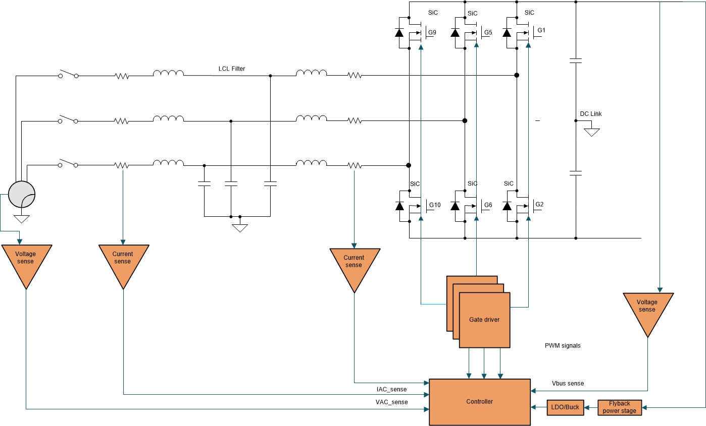
Figure 3-4 shows the typical configuration of a two-level three-phase PFC. The six-switch boost-type rectifier features a very simple circuit topology and easy control. It facilitates bidirectional power flow and can achieve a high power factor with reasonable efficiency.
 Figure 3-4 Two-level PFC.
 Since this topology is a two-level topology, it requires high-voltage blocking switches to block the entire DC link voltage. For example, in an 800-V DC link voltage application, a 1200-V rated blocking capacity Silicon Carbide (SiC) is required for the power stage. One of the drawbacks of this topology is the bulky filter inductor which it requires to regulate the input current THD to low values. Hence, the power density is low compared to the other competitive three-level topologies which are documented in Section 3.4, Section 3.5, and Section 3.6. Also, the peak voltage stress on the devices is very high which affects the long-term reliability of the semiconductor and other passive devices used in the power stage. Finally, the electromagnetic interference (EMI) performance of the converter is significantly lower when compared to other popular multilevel PFC topologies.