SLUUCC4A October   2020  – September 2021 TPS92520-Q1


  1.   Trademarks
  2.   General Texas Instruments High Voltage Evaluation (TI HV EMV) User Safety Guidelines
  3. 1Description
    1. 1.1 Typical Applications
    2. 1.2 Warnings
    3. 1.3 Connector Description
  4. 2Performance Specifications
  5. 3Performance Data and Typical Characteristic Curves
    1. 3.1 1.5A CC BUCK SW-Node Voltage Waveform
    2. 3.2 Start-up Waveforms
    3. 3.3 PWM Dimming
  6. 4Schematic, PCB Layout, and Bill of Materials
    1. 4.1 Schematic
    2. 4.2 Layout
    3. 4.3 Bill of Materials
  7. 5Software
    1. 5.1 Demonstration Kit Software Installation for LEDMCUEVM-132 Board
      1. 5.1.1 Installation Overview
    2. 5.2 Step-by-Step Installation Instructions
    3. 5.3 Installation Error Recovery
    4. 5.4 Checking for Updates
  8. 6TPS92520EVM-133 Power Up and Operation
    1. 6.1 Power Up and Operation at VINx < 40 V
    2. 6.2 MCU Control Window
    3. 6.3 SPI Command Window
    4. 6.4 Watchdog Window
    5. 6.5 GUI Devices Window
      1. 6.5.1 Channel 1 or 2 Sub-Window: Settings, Measurements, and Faults
      2. 6.5.2 Device Sub-Window: Shared Device Settings, Measurements, Register Info, and Limp Home
    6. 6.6 Limp Home Mode Window
  9. 7Revision History

Device Sub-Window: Shared Device Settings, Measurements, Register Info, and Limp Home

The Device window show a variety of measurements, faults, and settings for the device that are not specific to a channel, see Figure 6-27.

GUID-20200824-CA0I-4HPK-9JCK-WTQ9PSWFPKGD-low.gifFigure 6-27 Device Window - Channel and Systems Voltage Measurements.
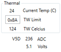
The Thermal window, Figure 6-28, shows the Current Temp which is a reading of the TEMPL/H registers. The TW Limit is a setpoint for the thermal warning limit that is defined in the TWLMT register. If the Current Temp exceeds the TW Limit then the TW bit is set. The Device window also shows the measured voltage of the V5D pin using the internal ADC.
GUID-20200908-CA0I-63B9-STLL-TQ6WR6FKNZTR-low.gifFigure 6-28 Temperature, V5D Measurement, and TW Setpoint.
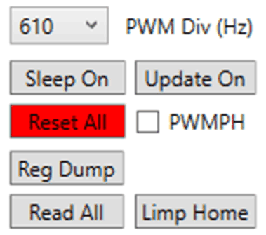
The pull-down menu for PWM Div (Hz) selects the PWM frequency that is to be used by both channels if the PWM Source Internal box is selected for that channel. The SLEEP button sets the SLEEP bits such that it goes into a low-power mode yet still keeps all the register information. The Limp Home button opens up a window with the limp home settings, see the Limp Home Mode Window section. The Update button initiates the polling of all the registers and continually refreshes the GUI with the information from the EVM. It is important to note that when using the Update mode, that faults can occur and be visually missed because the register reads clear the faults in the polling cycle. The Read All button performs a single read of all the registers and updates the GUI. The Reg Dump button does a read of all the registers and creates a .txt file with all the register information in the local drive at C:\Texas Instruments\TPS92518, 520, 682 LaunchPad Evaluation Software location. The Reset All button put the TPS92520-Q1 to its factory default settings.
GUID-20200824-CA0I-0KZ6-6CVD-H3SLFHNGKKFD-low.gifFigure 6-29 Internal PWM Frequency Set-Point, Sleep Mode, Reading Registers, and Limp Home Mode.

The Faults window, see Figure 6-30, allow for the selection of the Fault Timer duration in ms, which is set by the IFT bits. The Reset Flt Pin button clears the FPINRST bit and release the nFLT pin. The Stdalone box indicates that the STANDALONE bit is set and is in stand alone mode. The V5AUV box indicates that an under voltage fault has occurs at the V5A pin. The TW box indicates an overtemperature thermal warning fault has occurred. The PC box indicates that the PC (power cycle) bit is set, which happens at power up and is considered a fault. The PC bit must be cleared by reading the STATUS3 register and must be cleared before the channels can be enabled. There are several faults that if triggered must be read before operation can continue and they are covered in the Faults window.
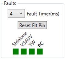
GUID-20200824-CA0I-VGGQ-VBWL-CQQ6WZDZWCR2-low.gifFigure 6-30 Fault Timer, Flags, and Resetting of Faults .