SLUUCD4 April 2021 TPS92682-Q1
- Trademarks
- General Texas Instruments High Voltage Evaluation (TI HV EMV) User Safety Guidelines
- 1Description
- 2REACH Compliance
- 3Performance Specifications
- 4Performance Data and Typical Characteristic Curves
- 5Schematic, PCB Layout, and Bill of Materials
- 6Software
- 7TPS92682EVM-125 Power UP and Operation
7 TPS92682EVM-125 Power UP and Operation
To start the EVM operation, connect the header J10 on TPS92682EVM-125 to the header J2/J4 on the LaunchPad, and the header J11 to the header J1/J3, using two included ribbon cables as shown in Figure 7-1.
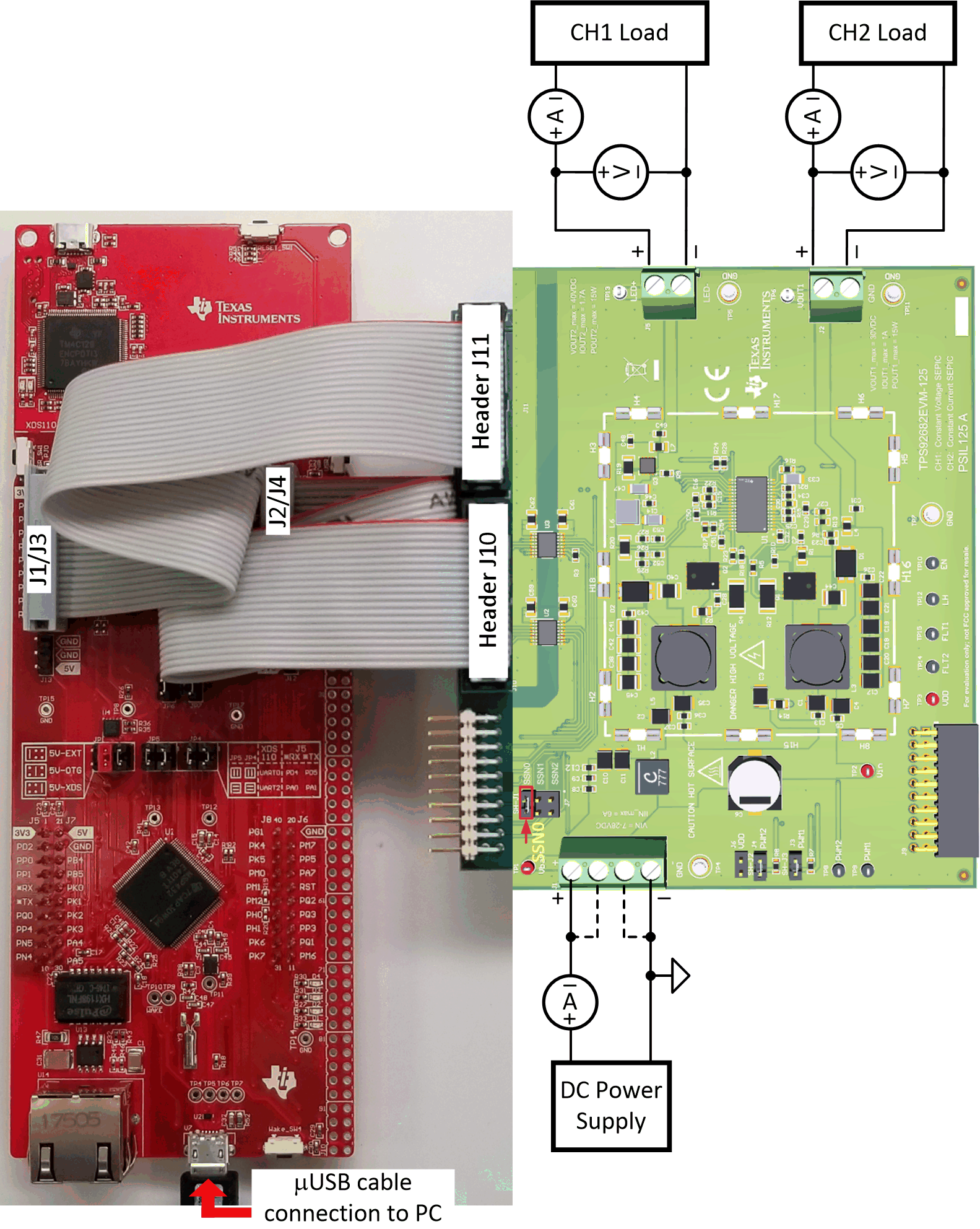 Figure 7-1 LaunchPad
Connection to TPS92682EVM-125
Figure 7-1 LaunchPad
Connection to TPS92682EVM-125Apply power (12 V) to the TPS92682EVM-125 board (terminal J1). Connect a resistive or a an electronic current sink load to the output of channel-1, terminal J2. Connect LED loads to the output of channel-2, terminal J5. Ensure that the loads are such that the maximum input and output current, maximum output power and maximum output voltage indicated on the EVM are not exceeded.
Run the program LED_Controller_GUI_LP.exe, located at the ":\Texas Instruments\TPS92682 LaunchPad Evaluation Software", to start the GUI. The window shown in Figure 7-2 opens.
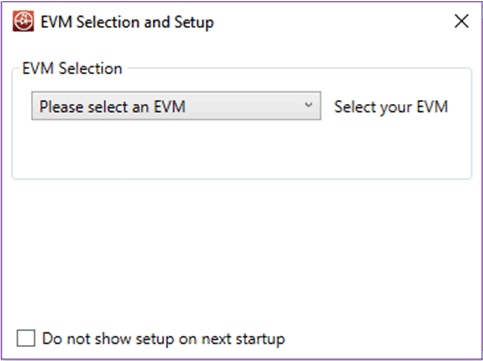 Figure 7-2 GUI Setup Screen 1
Click the EVM selection drop-down menu. Select TPS92682 CC - PSIL070.
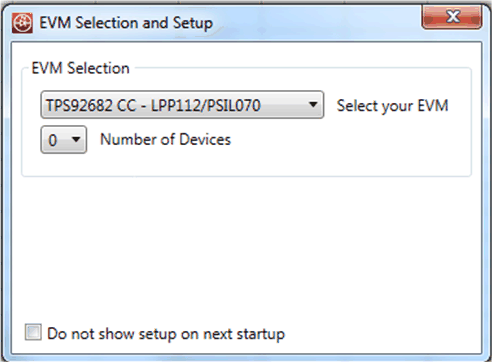 Figure 7-3 GUI Setup Screen 2
On the screen shown in Figure 7-3, select 1 as the number of devices. A new tab appears as shown in Figure 7-4. Select 682 for Device Type. Select 0 for Desired Address. Click Add Device.
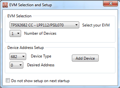 Figure 7-4 GUI Setup Screen 3
The main GUI window appears as shown in Figure 7-5. This window includes three sub-windows:
- MCU Control Box (1): includes controls for external PWM
- SPI Command Box (2): is used to manually read from and write to the registers on the SPI BUS
- Devices Box (3): is the main GUI control window to configure the TPS92682-Q1 device
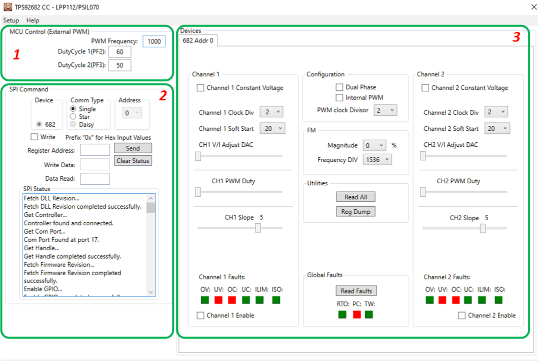 Figure 7-5 GUI, Main
Window