SLWU079D March 2012 – April 2016
-
TSW140x High Speed Data Capture/Pattern Generator Card
- Trademarks
- 1 Functionality
- 2 Hardware Configuration
- 3 Software Start up
- 4 ADC Data Capture Software Operation
- 5 TSW1400 Pattern Generator Operation
- 6 TSW1405 Functional Description
- 7 TSW1406 Functional Description
- 8 Revision History
6.2.1 Channel Selection
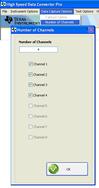
Because the TSW1405 has limited memory for sample capture, the GUI makes provision for selecting the number of channels from which to capture samples. This is a feature in the GUI that is not needed for the TSW1400, so there is a GUI popup dialog box for the TSW1405 that is not used for the TSW1400, as shown in Figure 21.
If a device is selected in the GUI that has more than one channel available, the Channel Selection Dialog window will let the user select one or more channels to be used for capture. If two, four or eight channels are selected, then samples from those channels are captured into the capture memory simultaneously.
 Figure 21. Number of Channels Selection
 The TSW1405 has enough internal memory in the FPGA to capture as many as 65536 samples of 16bit data. The 65536 samples will be automatically allocated to one, two, four or eight channels depending on the channel selections set in the GUI. If one channel is selected for capture, then the record length for that channel will be 65536 samples. If two channels are selected for capture, then each channel will get a record length of 32768 samples. Four channels will cause a record length of 16384 samples to be captured for each channel, and eight channels will capture 8192 samples for each channel.