SNVA853C December 2019 – March 2024 LMZ10500 , LMZ10501 , LMZ20501 , LMZ20502 , LMZ21700 , LMZ21701 , LMZ30604 , LMZ31506 , LMZ31520 , LMZ31530 , LMZ31704 , LMZ31707 , LMZ31710 , LMZ34202 , LMZ35003 , LMZ36002 , LMZM23600 , LMZM23601 , LMZM33602 , LMZM33603 , LMZM33604 , LMZM33606 , TLVM13610 , TLVM13630 , TLVM13640 , TLVM13660 , TLVM23615 , TLVM23625 , TPS82085 , TPS82130 , TPSM265R1 , TPSM33615 , TPSM33625 , TPSM365R3 , TPSM365R6 , TPSM53604 , TPSM5601R5 , TPSM5601R5H , TPSM5601R5HE , TPSM560R6 , TPSM63603 , TPSM63604 , TPSM63606 , TPSM63608 , TPSM63610 , TPSM84424 , TPSM84624 , TPSM846C23 , TPSM846C24 , TPSM84824
4.3.2 Method 2 - Solder Surface Area
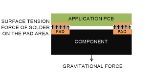
 Figure 4-3 Component Held by the Solder Surface Tension Across the Pad Area
This method of evaluating the back side mounting feasibility was developed by Liu, Geiger, and Shangguan. The model considers the overall area of the component pads and dictates 47mg/mm2 of maximum recommended ratio of component mass to total pad area.