SPRAD20 March 2022 AM2631 , AM2631-Q1 , AM2632 , AM2632-Q1 , AM2634 , AM2634-Q1
- Trademarks
- 1Introduction
-
2A Step-by-Step Guide to Running a Traction
Inverter
- 2.1 Create Real Time Debug Interface
- 2.2 Configure Control Peripheral and ADC Interrupt With Sysconfig
- 2.3 Configure Gate Driver Interface With MSPI
- 2.4 Get Samples From ADC and Read Samples Via CCS
- 2.5 Generate Space Vector PWM and Drive Motor in Open Loop
- 2.6 Close Current Loop With Mock Speed
- 2.7 Add Software Resolver to Digital Converter
- 2.8 Close Speed Loop With Rotor Speed
- 3A Brief Guide to Code Migration
- 4Summary
- 5References
2.6.1 Add Transformations and Read Id-Iq in Open Loop
To close current loop, the following transformations need to be added. Line 1 is clark transformation, and line 2 is park transformation. Similar functions can be found in CMSIS DSP library and others. The angle information is already included in the structure of motor1. The implementation here is similar to C28 program for TIDM-02009.
- clarke_run(&motor1);
- park_run(&motor1);
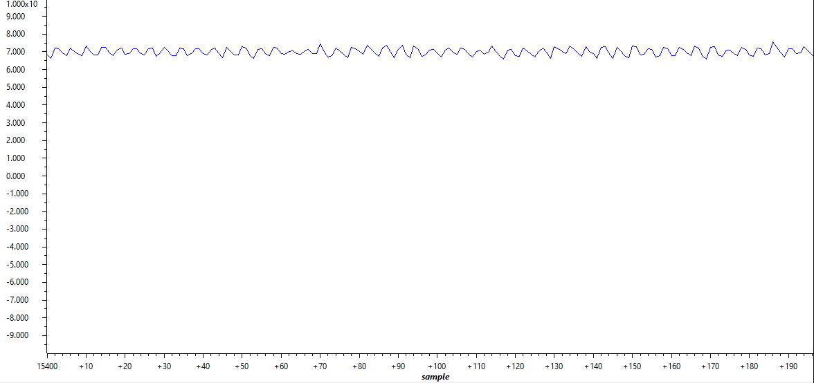
Ideally, Id and Iq are close to constant values during open loop steady state operation. In most cases, it is not difficult to read them in expression window. If graph view is desired, they can be added to graph window by following Section 2.4.3. Here are the setup for log pointers. Line 1 is Id and line 2 is Iq. The plotted Id is in and Iq is in Figure 2-37 and Figure 2-38.
- gLog_ptr[10] = &motor1.I_dq_A[0];
- gLog_ptr[11] = &motor1.I_dq_A[1];
 Figure 2-37 Open Loop Id
 Figure 2-38 Open Loop Iq