SWRA478D February 2015 – January 2019 CC1310 , CC1312PSIP , CC1312R , CC1314R10 , CC1352P , CC1352P7 , CC1352R , CC2640 , CC2640R2F , CC2640R2F-Q1 , CC2642R , CC2642R-Q1 , CC2650 , CC2650MODA , CC2652P , CC2652R , CC2652R7 , CC2652RB , CC2652RSIP
7.1 Modifying the rfPacketTX Example
Using SmartRF™ Studio [25], you can find the modifications that need to be done in smartrf_settings.c to change, for example, the output power to 10 dBm (see Figure 7-9).
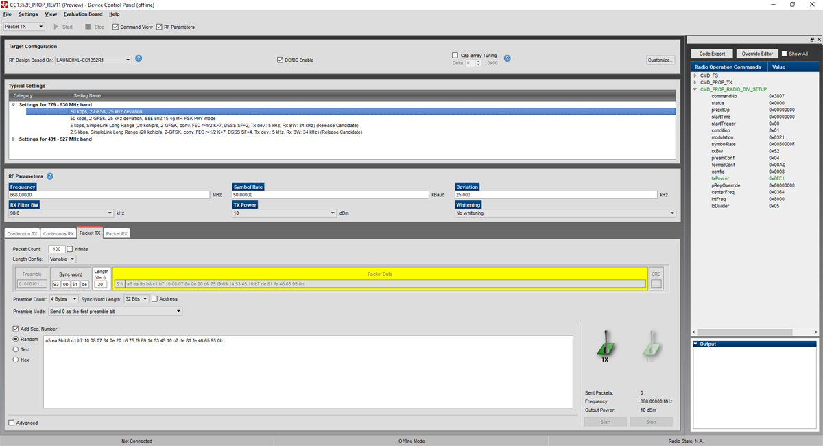 Figure 7-9 Using SmartRF Studio to Find
New Settings
Figure 7-9 Using SmartRF Studio to Find
New SettingsAfter changing the output power by modifying the smartrf_setting.c file, as shown in Figure 7-10, the measurements were repeated.
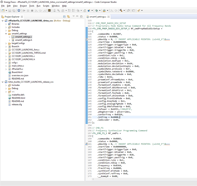 Figure 7-10 Modifying the
smartrf_settings.c File
Figure 7-10 Modifying the
smartrf_settings.c FileFigure 7-11 shows the current profile for transmitting a packet achieved with using EnergyTrace. It shows a TX power consumption at +10 dBm (3.3 V) of 14.78 mA. Figure 7-12 shows the same profile, captured using the DC Power Analyzer. It shows a current consumption in TX of 14.4 mA. The data sheet numbers [7] for TX at +10 dBm is 14.3 mA.
Even if the numbers you get when using EnergyTrace is not as accurate as the ones obtained with the DC Power Analyzer, the numbers will be very useful when estimating current consumption for an application.
 Figure 7-11 Current Profile of TX
(EnergyTrace)
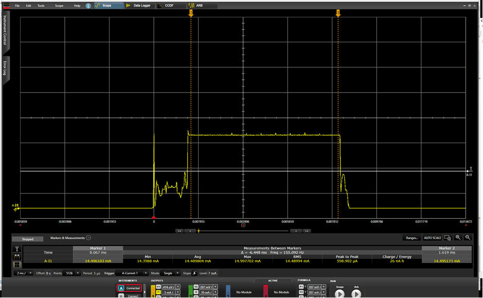 Figure 7-12 Current Profile of TX (DC
Power Analyzer)
Figure 7-12 Current Profile of TX (DC
Power Analyzer)It is not possible to accurately measure the Standby current when using EnergyTrace, but you can still use it to verify that the device is in Standby.
As described in Section 2, the CC13x2/CC26x2 have a built-in comparator that gives the optimal recharge interval at any time. In the previous measurements, no re-charge pulses have been seen.
If the packet interval, and hence the time in Standby, is doubled the recharge pulses should appear. In the rfPacketTX example, this can easily be done by including the POWER_MEASUREMENT define in rfPacketTx.c.
The packet interval is then changed from 500 ms to 5 s. The PACKET_INTERVAL also needs to change from 5 to 1.
/* Do power measurement */
#define POWER_MEASUREMENT
/* Packet TX Configuration */
#define PAYLOAD_LENGTH      30
#ifdef POWER_MEASUREMENT
#define PACKET_INTERVAL     1  /* For power measurement set packet interval to 1 s */
#else
#define PACKET_INTERVAL     500000  /* Set packet interval to 500000 us or 500 ms */
#endif
With these modifications, the re-charge pulses are easy to identify during the time in Standby (see Figure 7-13).
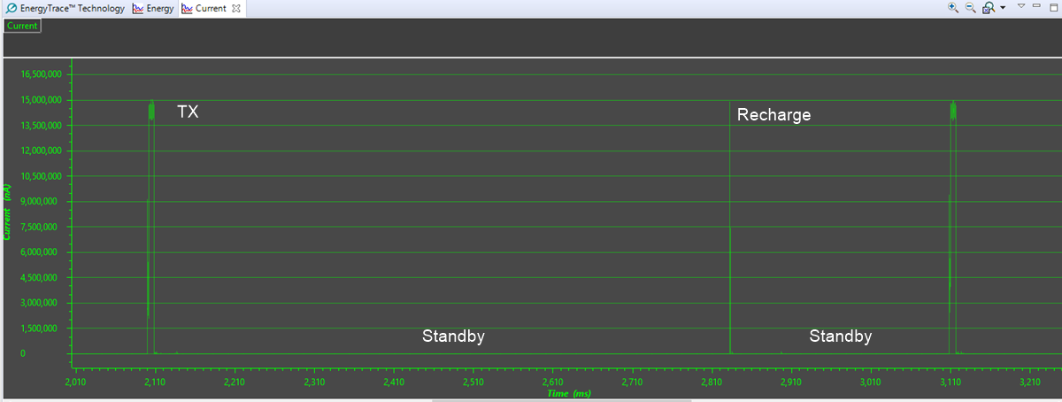 Figure 7-13 Recharge Pulses
For the average current consumption of an application, it is very important that the device always enters the lowest possible power mode. If, for some reason, there were things in the rfPacketTX examples that prevented the device from entering Standby in-between packets, the average current consumption would increase significantly. For the current profile shown in the previous code example, the average current consumption is 0.1 mA (see Figure 7-14).
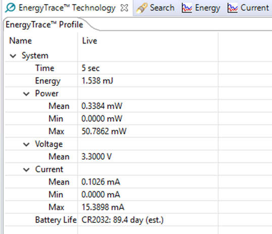 Figure 7-14 Average Current Consumption
When Device Enters Standby
Figure 7-14 Average Current Consumption
When Device Enters StandbyTo see how the current consumption will look like if the device is not entering Standby, a power constraint is set to disallow this power mode. This can be done with the following modification:
#include <ti/drivers/Power.h>
#include <ti/drivers/power/PowerCC26X2.h>
void *mainThread(void *arg0)
{
    RF_Params rfParams;
    RF_Params_init(&rfParams);
    Power_setConstraint(PowerCC26XX_SB_DISALLOW); // Prevent the device from entering Standby
Figure 7-15 shows what the current profile looks like, with an average current consumption of 1 mA (see Figure 7-16).
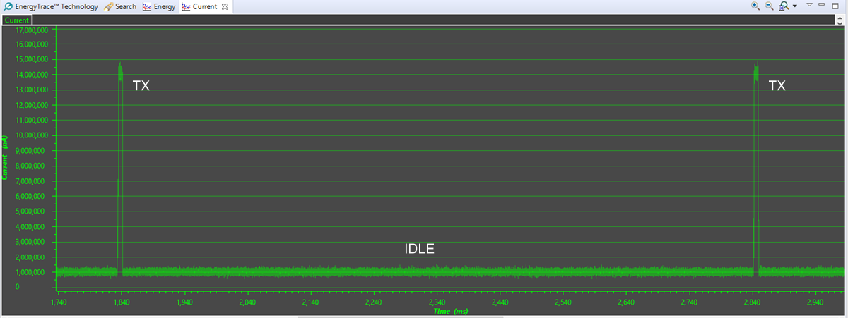 Figure 7-15 IDLE State Between
Packets
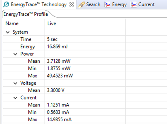 Figure 7-16 Average Current Consumption
When Device Does not Enter Standby