TIDUEY6 April 2021
- Description
- Resources
- Features
- Applications
- 5
- 1System Description
- 2System Overview
-
3Hardware, Software, Testing Requirements, and Test Results
- 3.1
Hardware Requirements
- 3.1.1
Hardware Overview
- 3.1.1.1
Control Module
- 3.1.1.1.1
Control Mother Board
- 3.1.1.1.1.1 Inverter Safing - UCC5870 ASC and Fault Control
- 3.1.1.1.1.2 DC-DC Safing
- 3.1.1.1.1.3 DC-DC Converter Secondary PWM Selection
- 3.1.1.1.1.4 Blower Fan Control
- 3.1.1.1.1.5 Voltage Monitor
- 3.1.1.1.1.6 Resolver Interface Control
- 3.1.1.1.1.7 Test Points on Control Module
- 3.1.1.1.1.8 General Purpose Ports
- 3.1.1.1.1.9 Connectors and Headers on Control Mother Board
- 3.1.1.1.2 Power Supplies
- 3.1.1.1.3 TCAN4550 module
- 3.1.1.1.4 Dual TCAN Module
- 3.1.1.1.5 Analog Back End Module
- 3.1.1.1.6 Resolver Analog Front End Module
- 3.1.1.1.1
Control Mother Board
- 3.1.1.2 Inverter Module
- 3.1.1.3 DC-DC Bidirectional Converter Module
- 3.1.1.1
Control Module
- 3.1.1
Hardware Overview
- 3.2 Resource Mapping
- 3.3 Test Setup
- 3.4 Test Results
- 3.1
Hardware Requirements
- 4General Texas Instruments High Voltage Evaluation (TI HV EVM) User Safety Guidelines
- 5Design and Documentation Support
- 6About the Author
3.1.1.1.1 Control Mother Board
- HSEC180 connector slot to host the control card for control processor (TMDSCNCDF28388D)
- DIMM100 connector slot to host the safety processor (TMS570)
- Connectors to connect to traction inverter module
- Connectors to connect to dc-dc converter module
- Connectors to host 5-V/5-A power supplies for the control unit and inverter gate driver power supply.
- Connectors to host 12-V/1-A power supply for the DC-DC converter gate driver and 15-V/0.5-A power supply for resolver
- Connectors to host analog back end module to process the analog signal feedback from inverter. The close proximity of this module to the processor slot is to increase integrity of analog signal chain.
- Connectors to host resolver module that act as an analog front end between the resolver and MCUs.
- Connectors to host CAN interface modules based on TCAN4550 and TCAN1042
- Module to help monitor various power supplies
- Module to control blower fan for inverter heatsink thermal dissipation
- Debug header to support JTAG and provide ETAS link
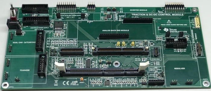
The bare control mother board is shown in Figure 3-2.
 Figure 3-2 Control Mother Board
12-V power from a battery or power supply is fed to the mother board through a power jack receptacle J14. A single pole double throw switch is used to turn on/ off the power to the control module. This 12-V power supply feeds two 5-V/5-A power supplies, one to supply power to entire control module (from which 3.3 V is obtained) and the other to primarily feed the inverter gate driver power supply. The 12-V power supply also feeds a SEPIC 12 power supply module to feed the dc-dc converter gate driver. For flexibility sake during testing, certain options are built in the mother board to select the choice of MCU for certain controls and choice of power supply for resolver interface. These are described in sections below